
CURTA DISASSEMBLY
NEW! Larger images
(press F11 to maxamize your screen)(since April 22, 1997) Last Update: August 20, 2021 -- THE CURTA REFERENCE
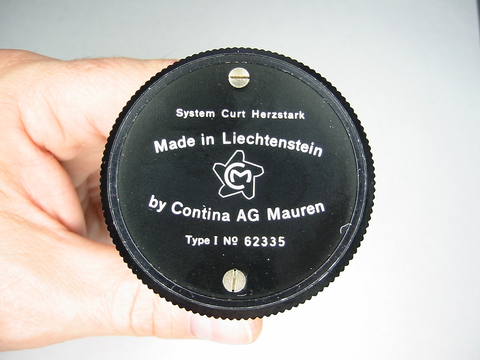
Start by removing the two screws on the bottom of the Curta |
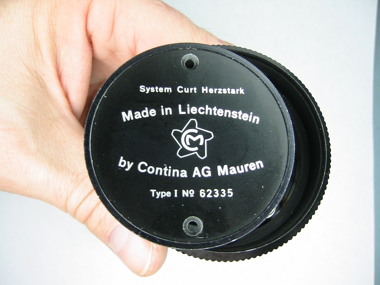
The plate will then lift out of the bottom. Be careful because the side can easily slide off. |
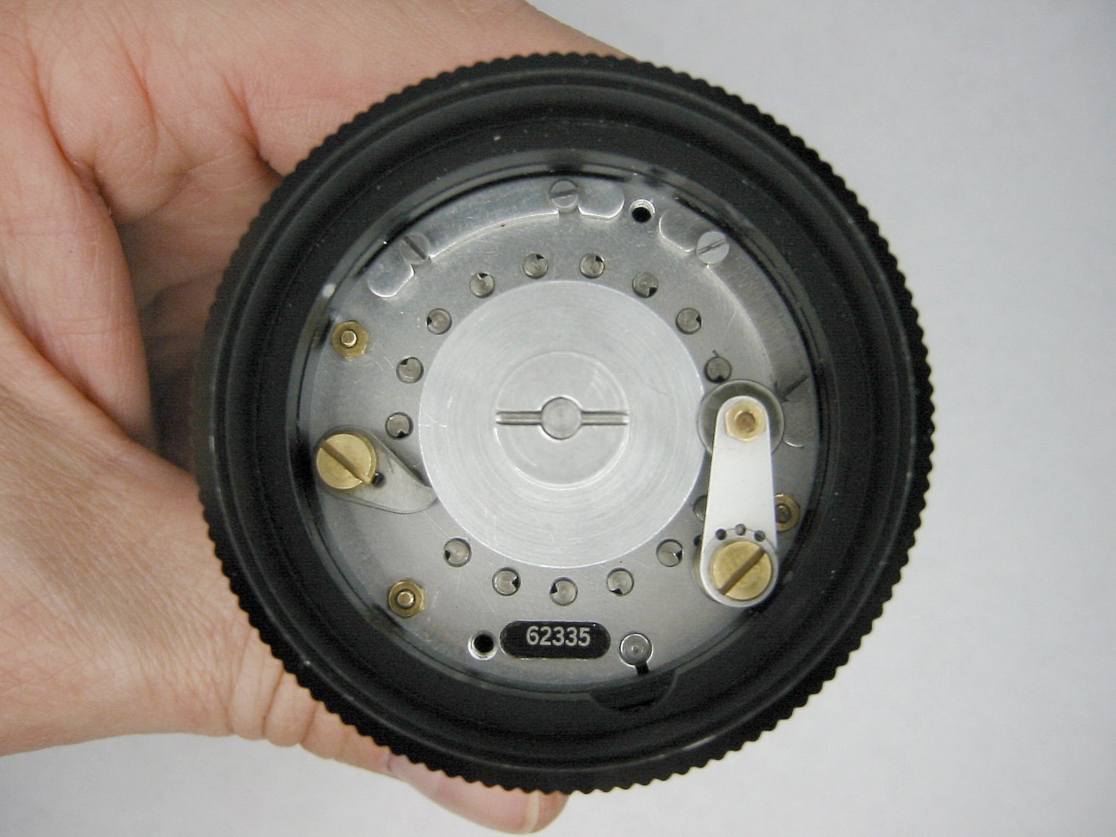
Here you can see the home position mechanism and the anti-reverse cam. Many of the Curtas also have their serial number on the bottom plate too. |
Now holding the top slide the side off the bottom. |
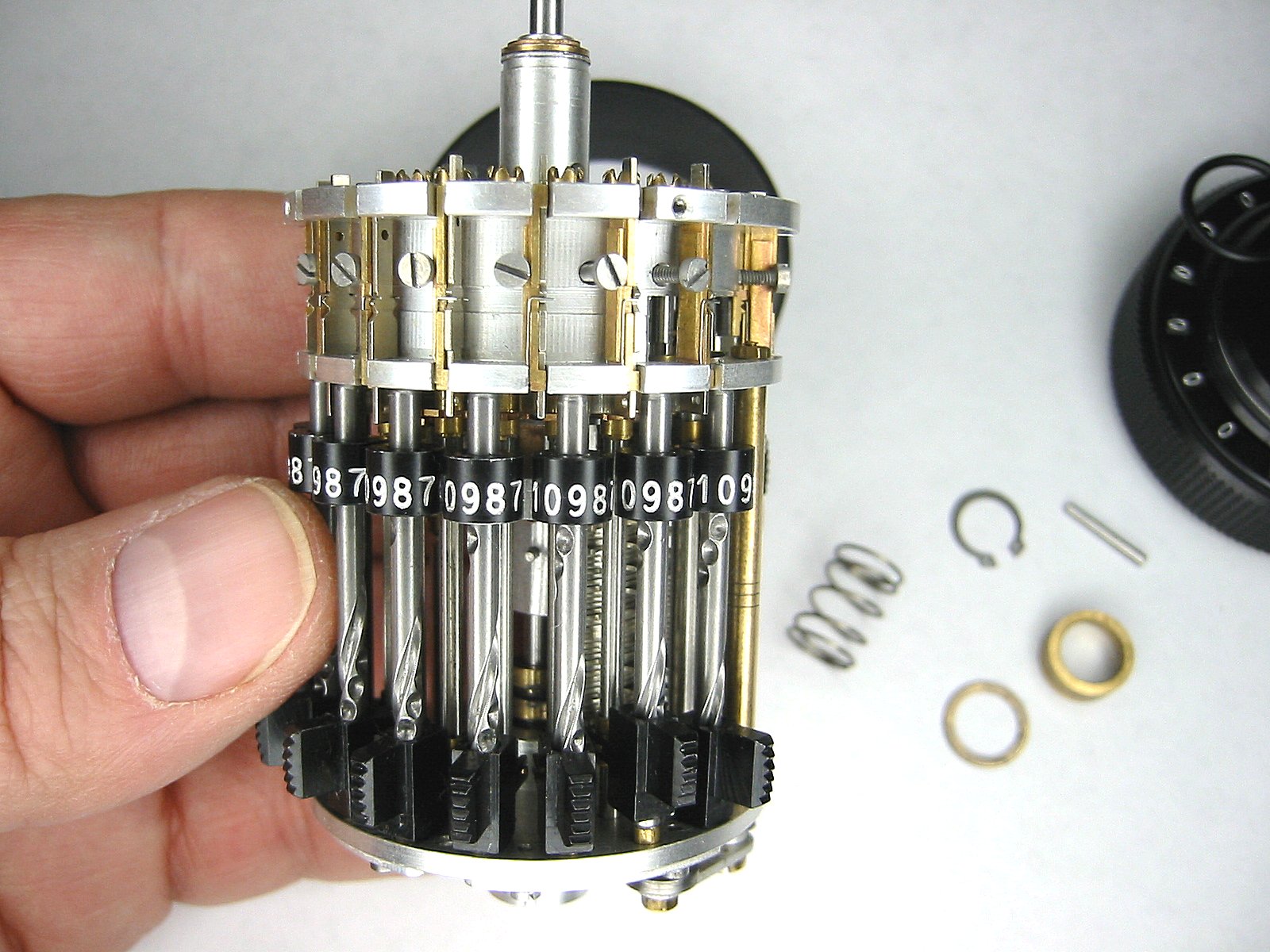
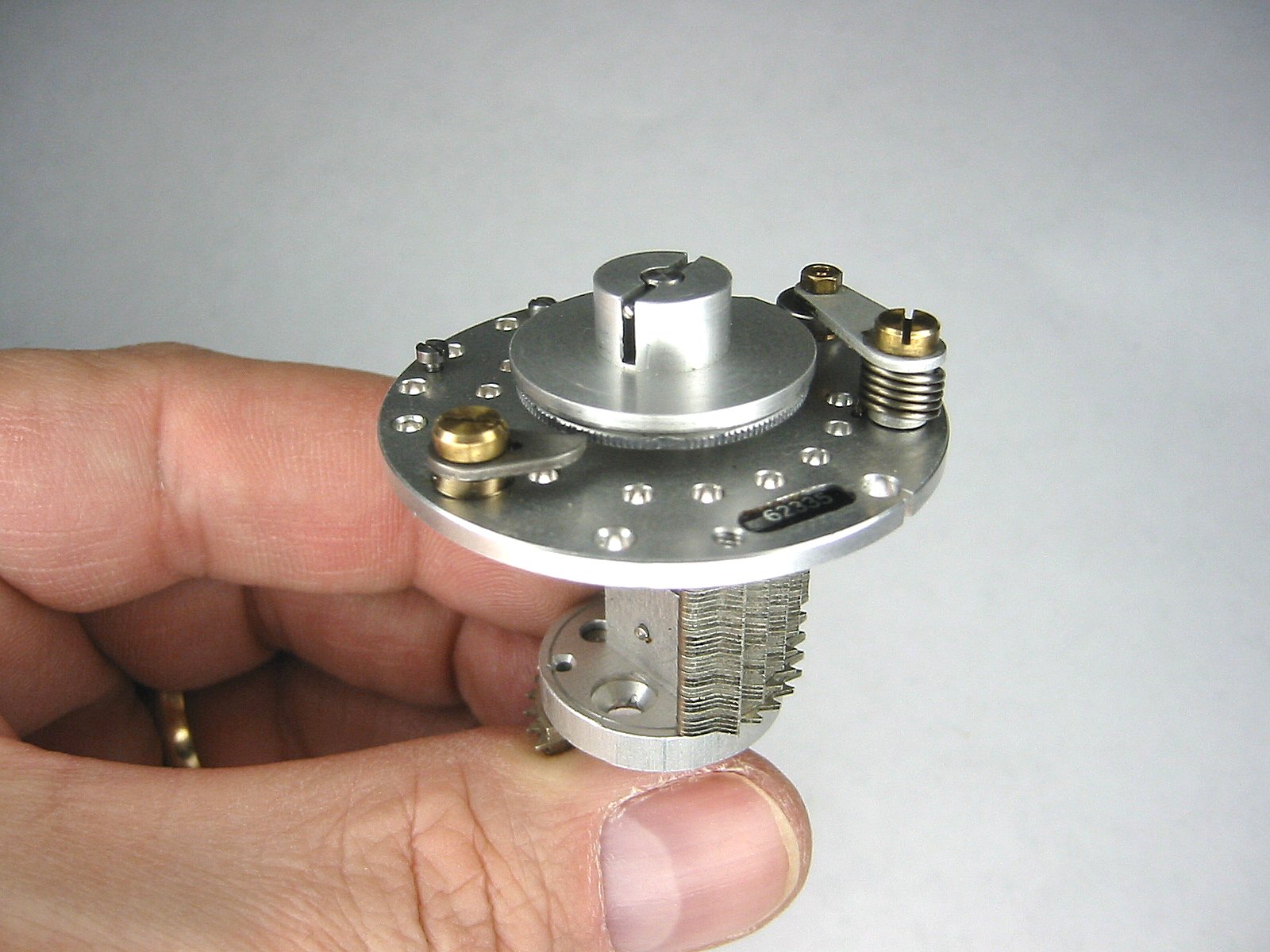
Now the lower mechanism of the Curta can be observed. |
A view of the top |
A view of the top from the other side. |
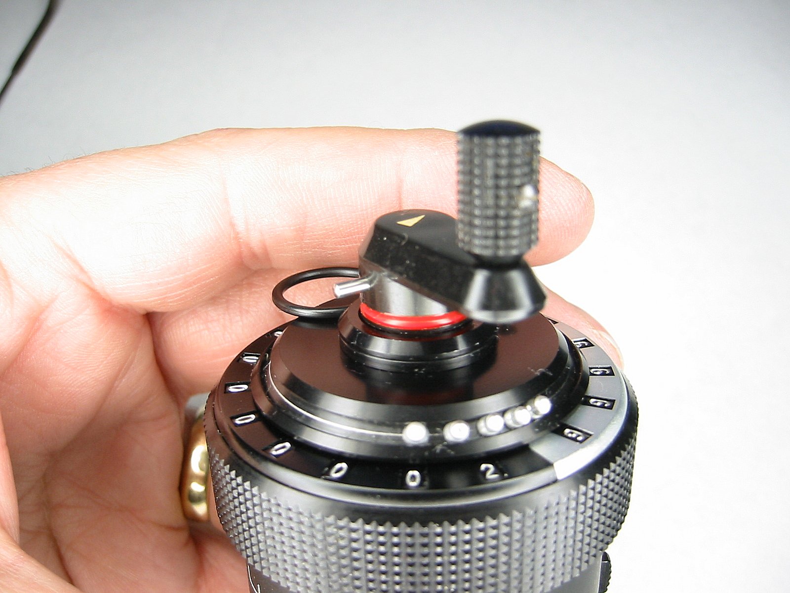
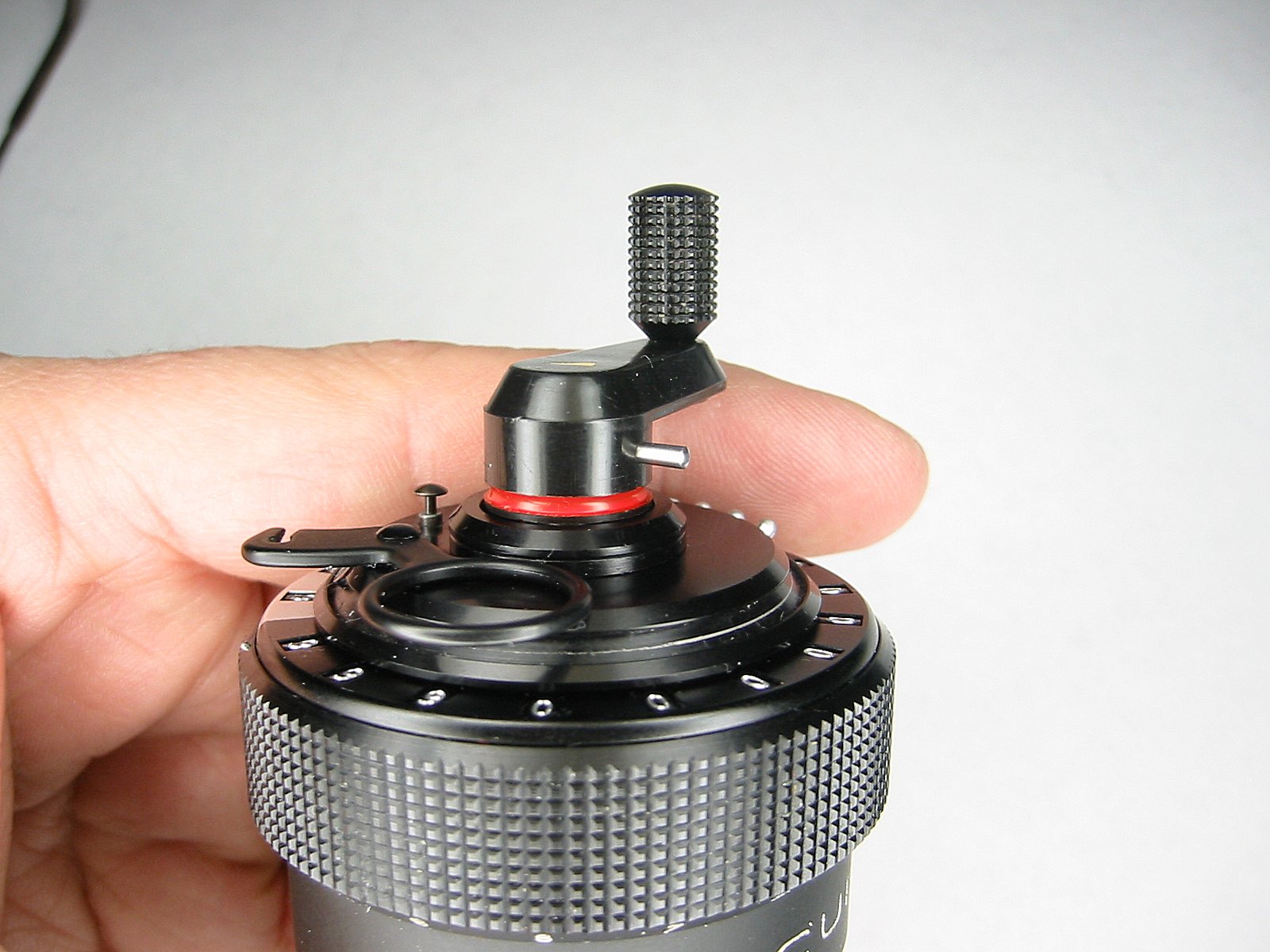
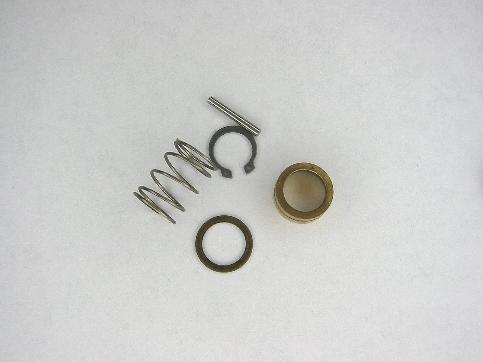
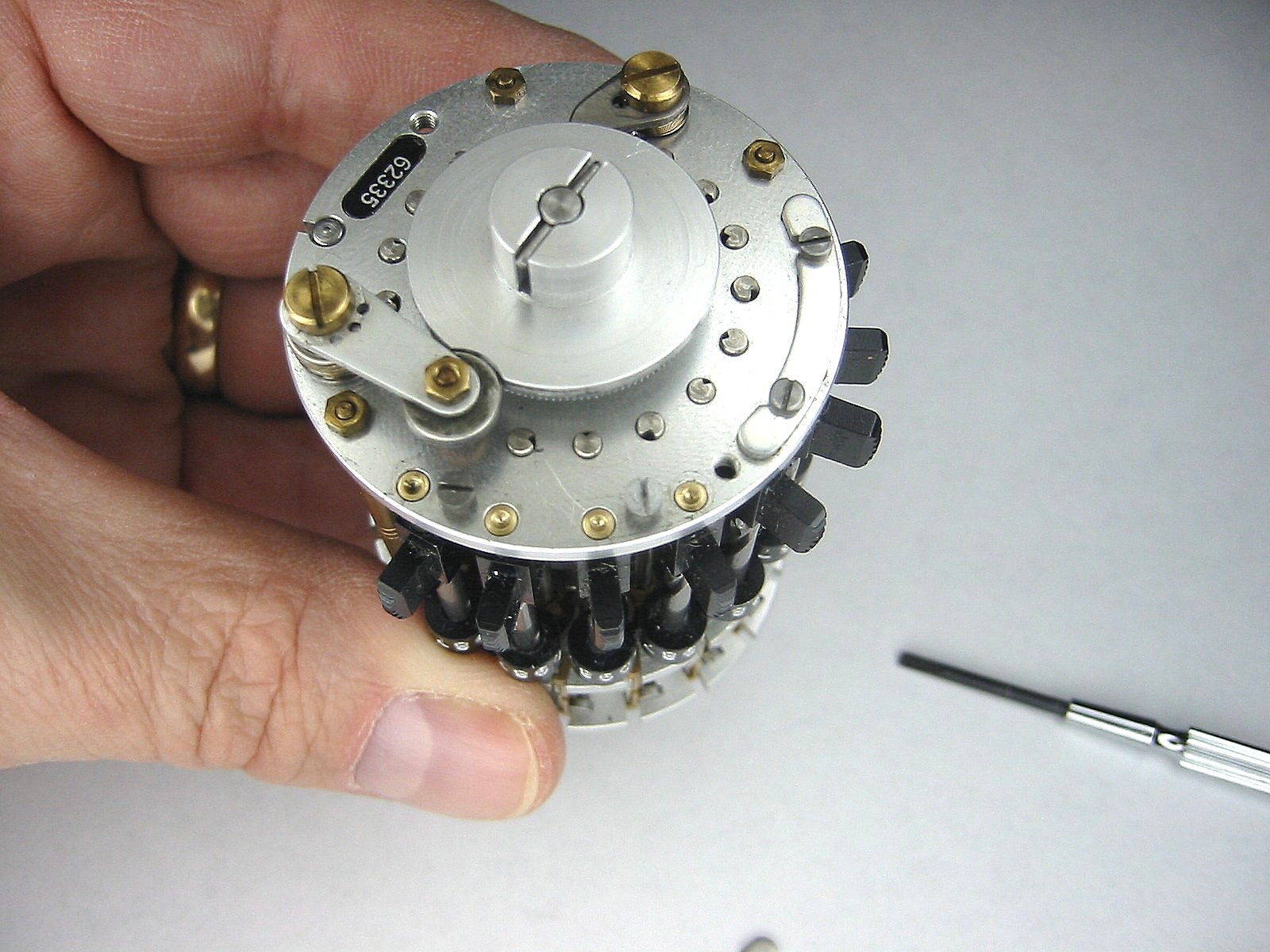
Once the pin is out the crank pulls off. Pull it up and turn backwards. It exposes the shaft and two circ lip. Remove only the lower, larger one. |
The crank knob can be removed from the crank by removing the screw. |
Be careful, I almost got shot in the eye the first time I removed the top. Cover the top with your hand. The brass ring secures the carriage pressure spring under it. |
Here's the Carriage pressure spring. There's a brass washer under the spring. |
Here are all of the top inner parts. |
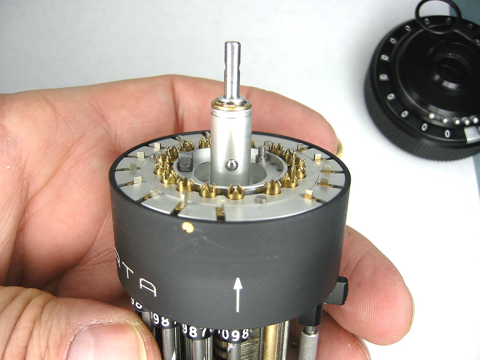
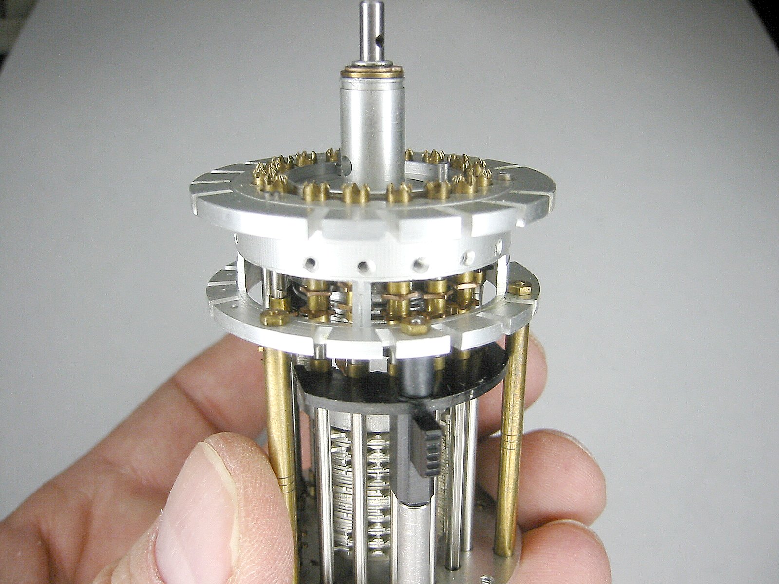
Lift the top off. Remove the ball rearing that's in the side on the lower part of the central shaft. This ball is used to prevent the top from being lifted after the crank has started turning. Now you can see the transmission shafts and the ten carry levers. Now remove the three screws holding the upper side on. |
Now you can see the entire ten carry mechanism. Be careful not to catch and bend the tiny ten carry springs. The tens carry springs are so small you cannot see them in this photo. |
The ten carry mechanism |
The ten carry mechanism |
The top assembly |
The bottom assembly |
Now we're going to remove the setting shafts. Start by partially loosening the two screws on the left plate. |
Slide the setting shaft plate off. Leave the screws in place. |
Here's the setting shaft plate. |
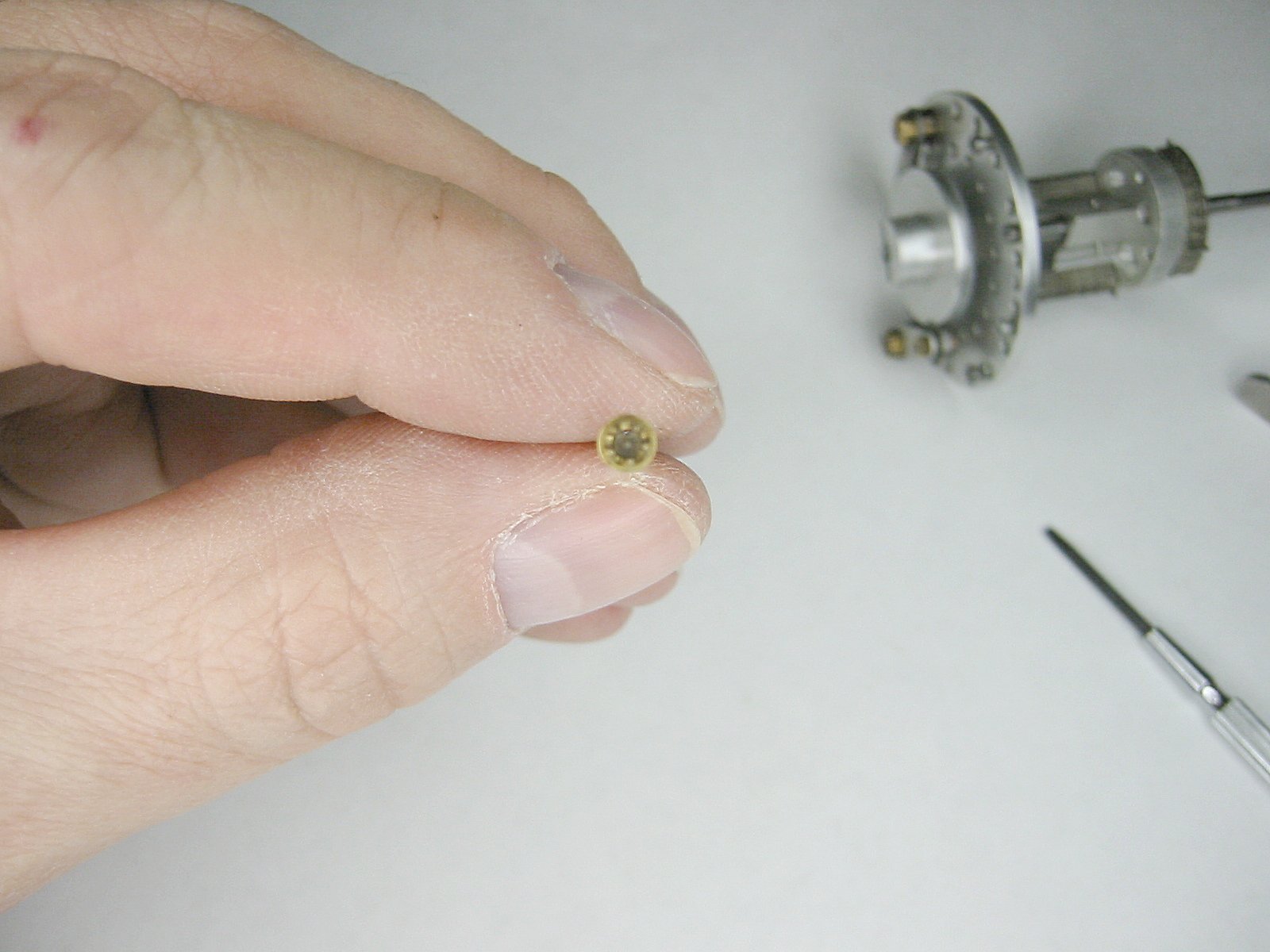
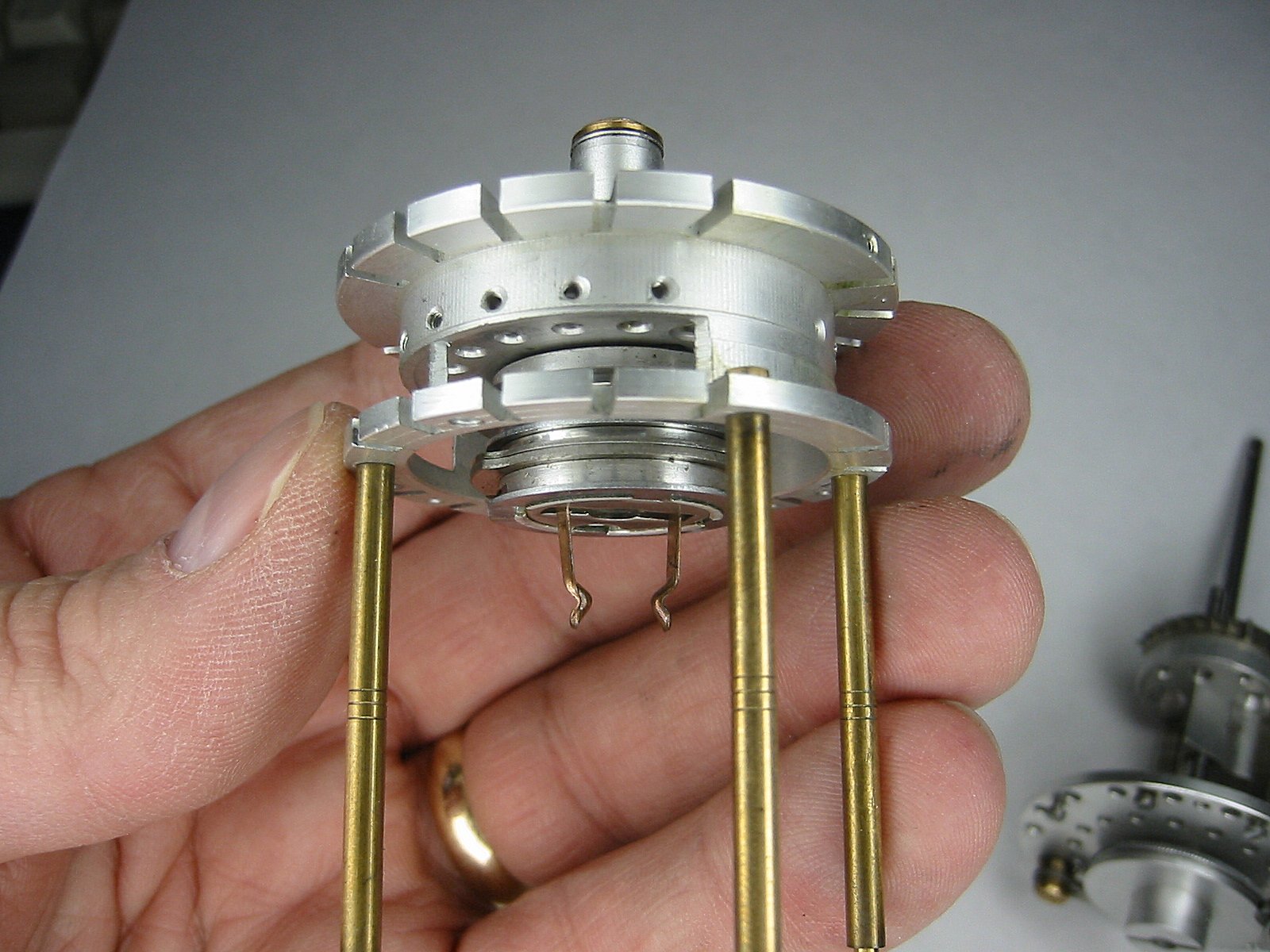
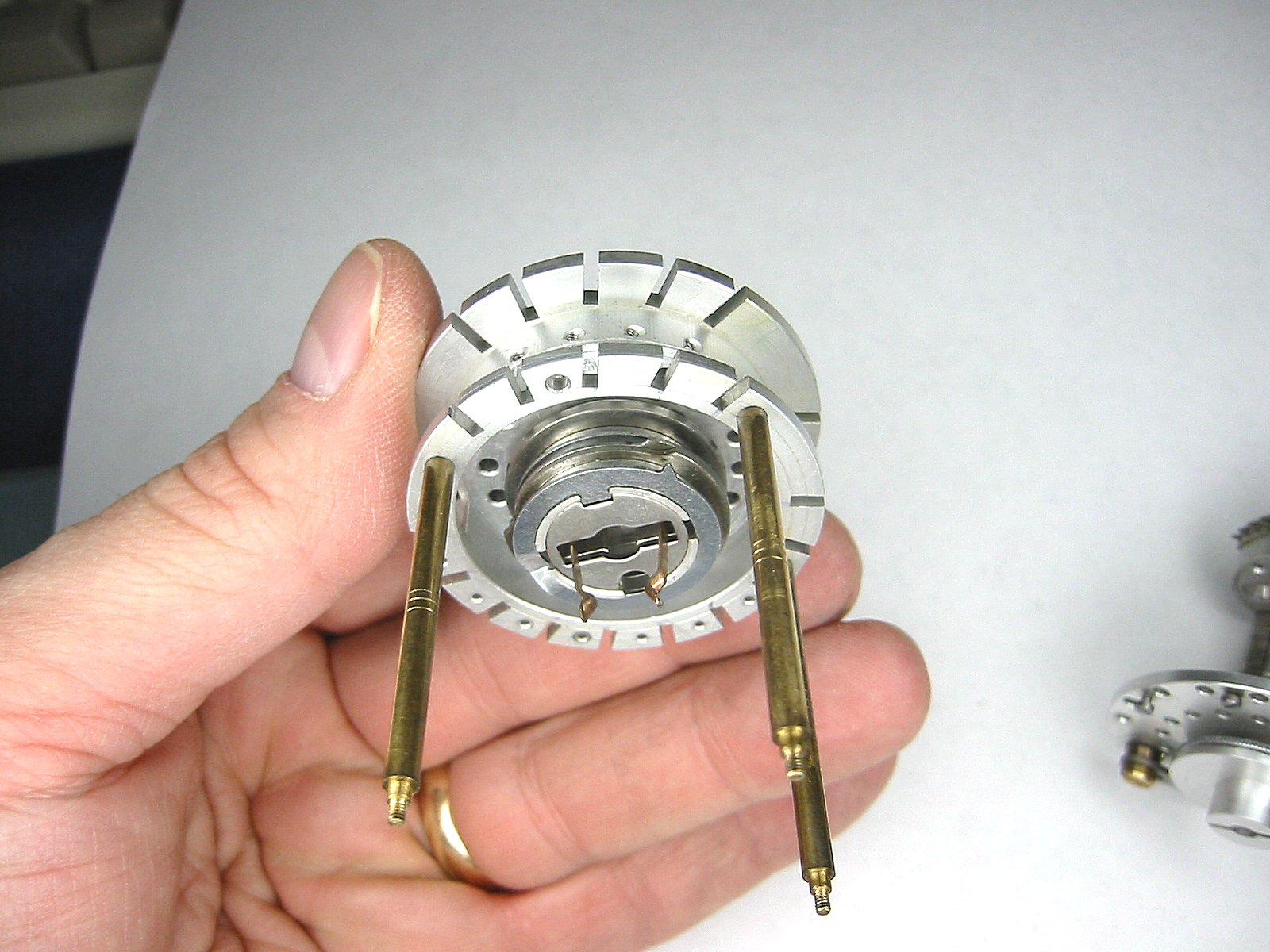
Now gently push up on the left most setting shaft. The setting shaft bearing will protrude out the bottom. Grab it with a pair of tweezers. Now remove the remaining three bearings. |
Now the setting shafts can be easily removed. |
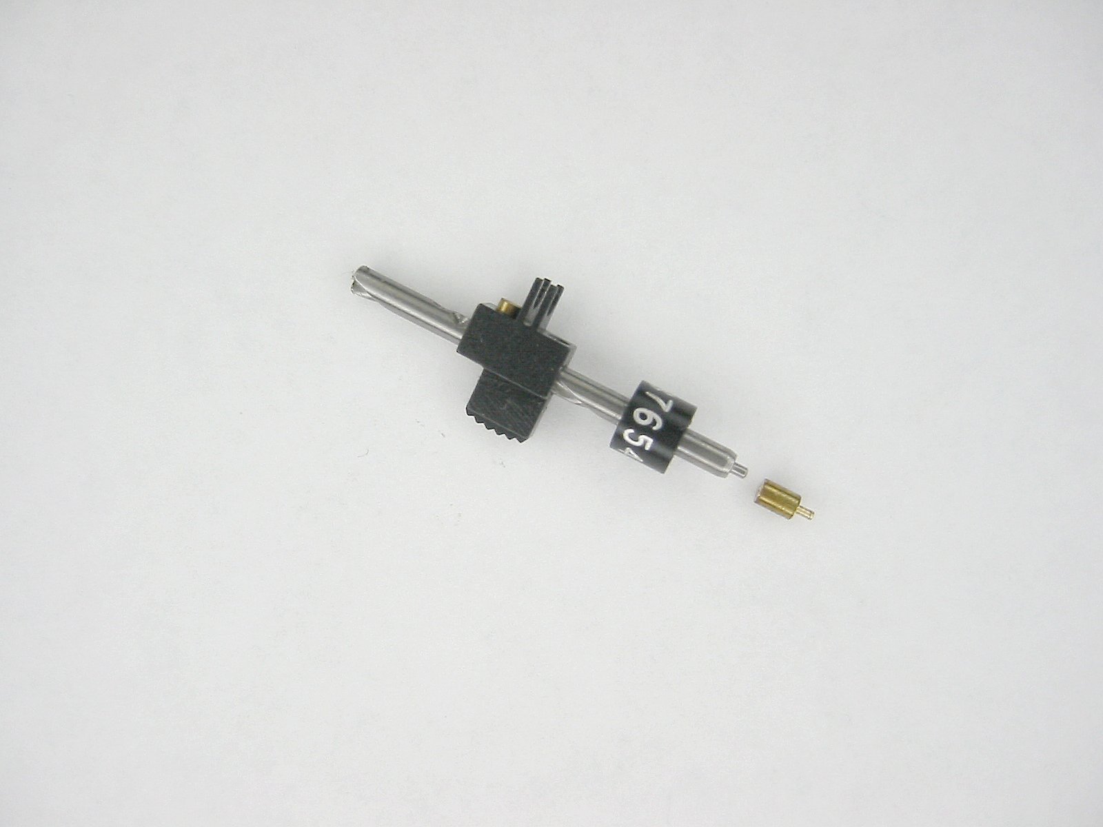
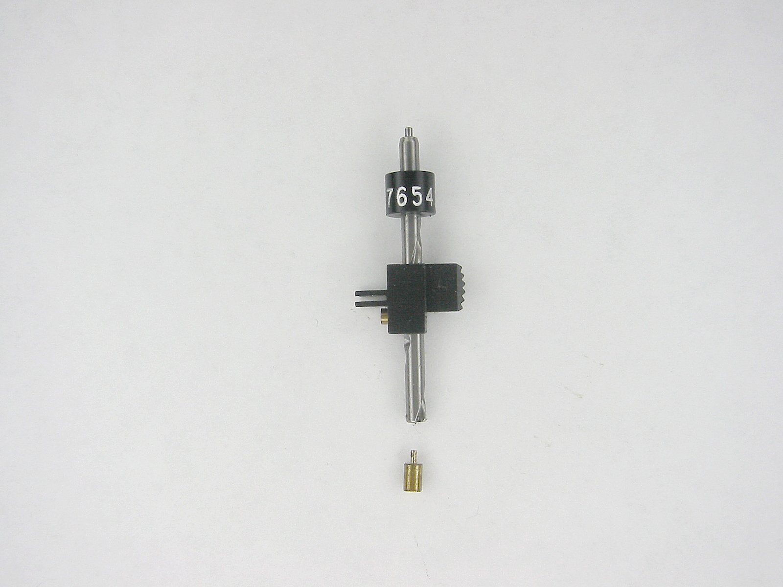
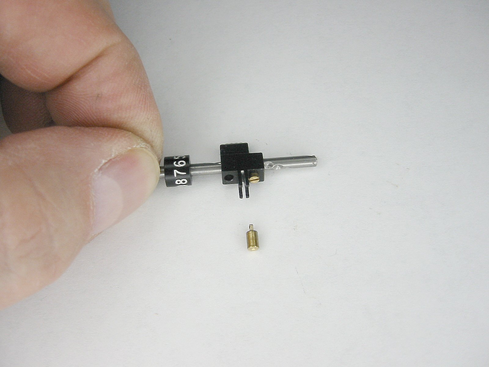
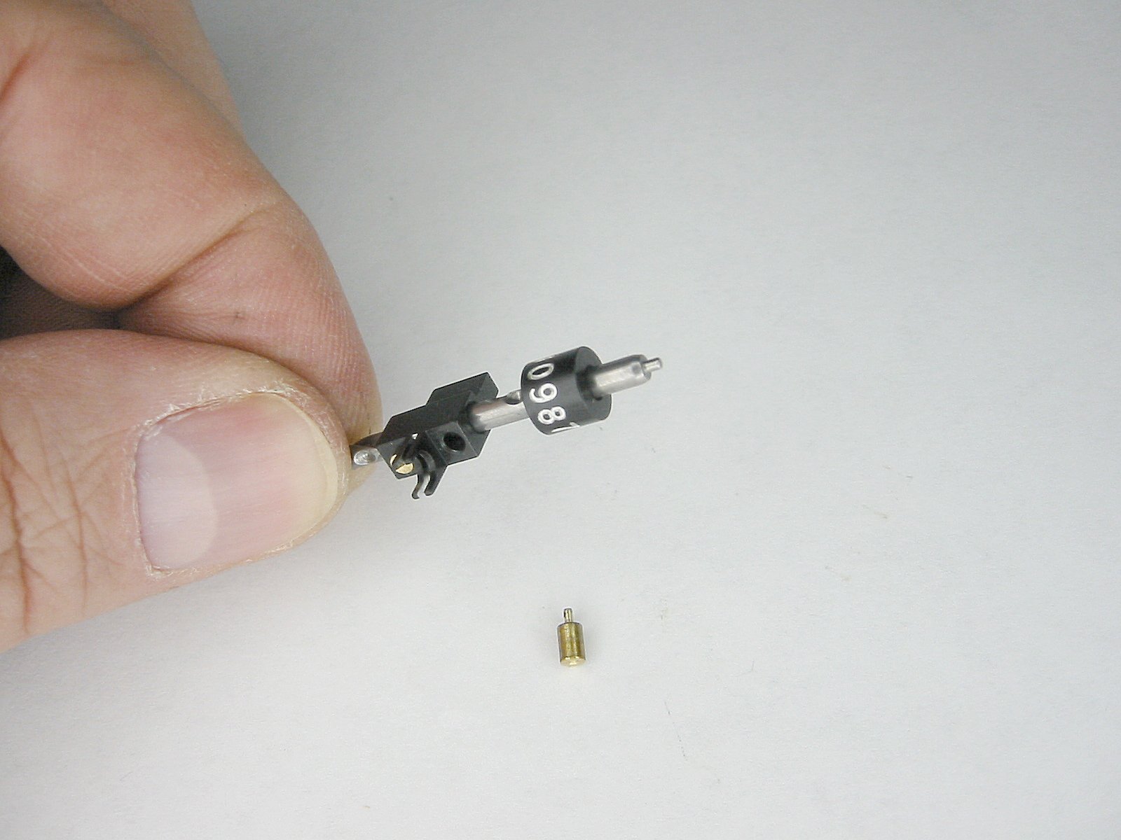
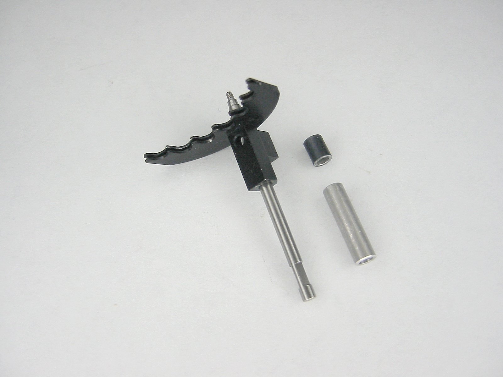
Here are some views of the setting shaft and it's bearing. DO NOT SLIDE the setting shaft lever off of the shaft. It contains a tiny spring and a ball bearing. I'm guessing that it would be hard as hell to get it back together. |
While I'm at it, DO NOT remove the decimal markers on the top and bottom of the Curta. They, too, contain a tiny spring and ball bearing. It must have taken me 30 minutes to wrangle the parts back into place after I removed a decimal marker!" |
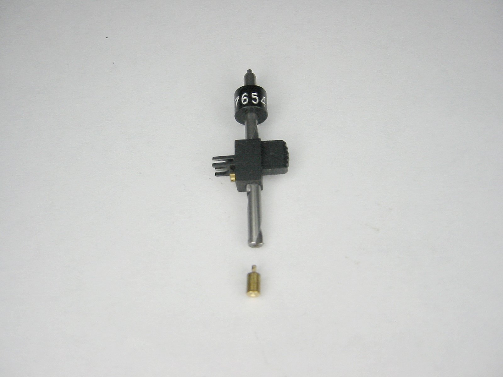
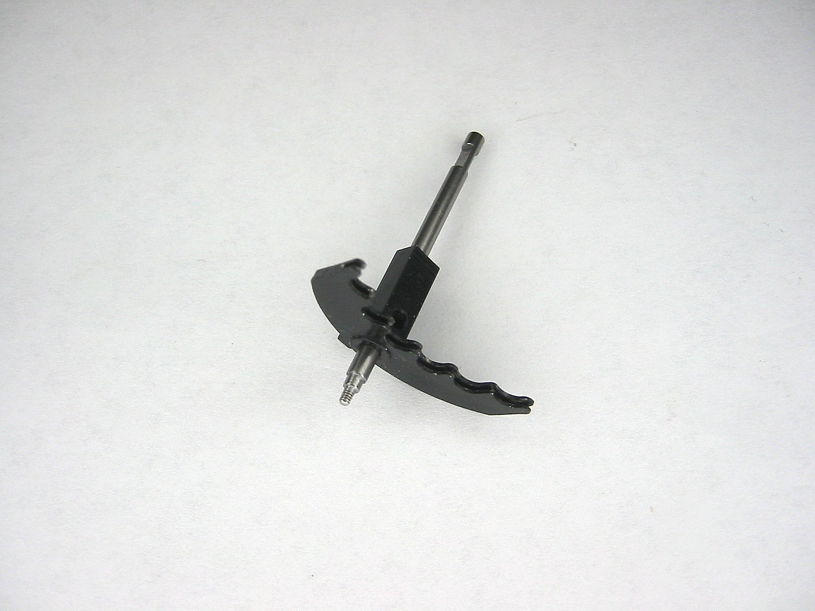
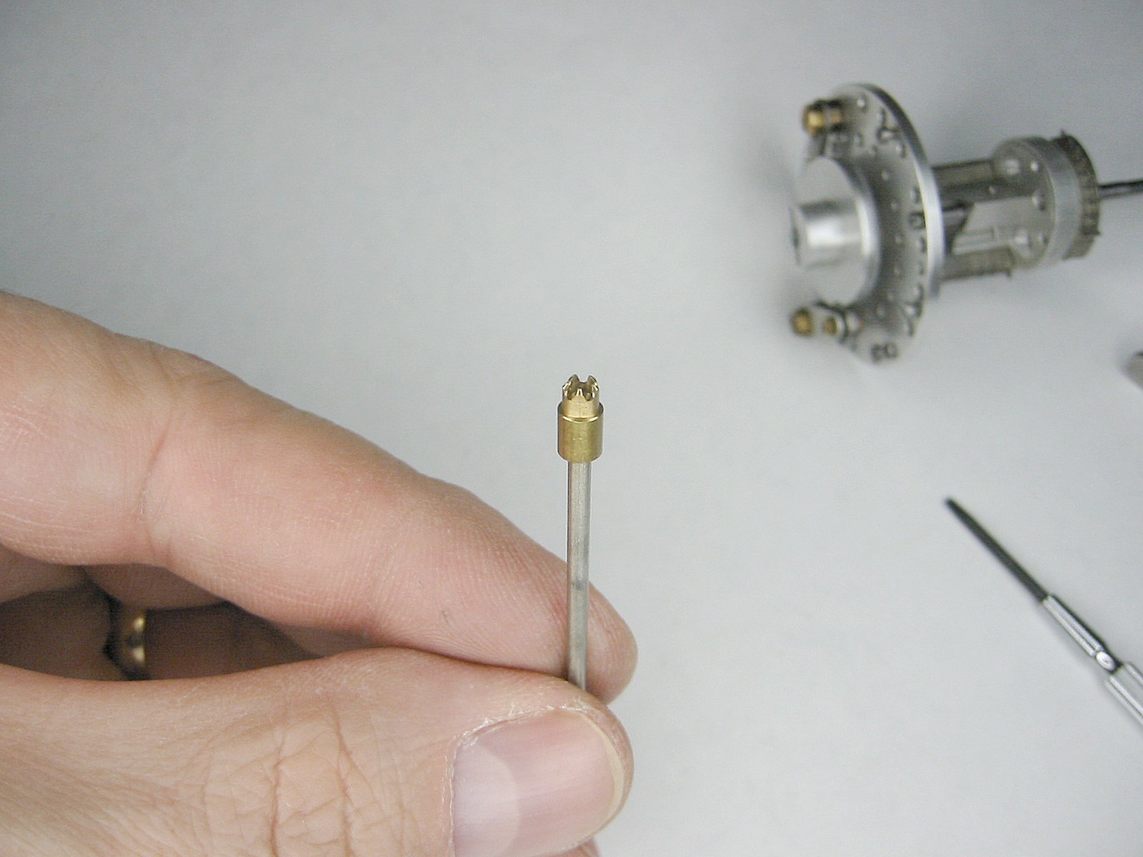
The Setting Shaft |
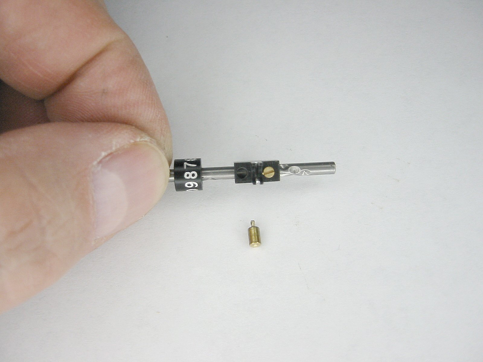
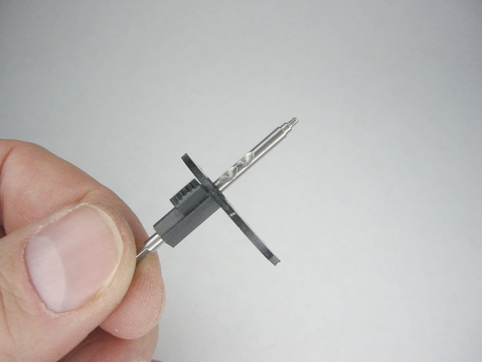
The screw in the knob follows the spiral groove in the setting shaft. The tip of the screw is precisely oriented to fit the angular groove...don't turn the screw! |
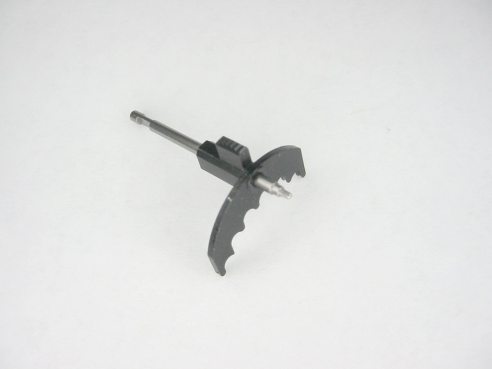
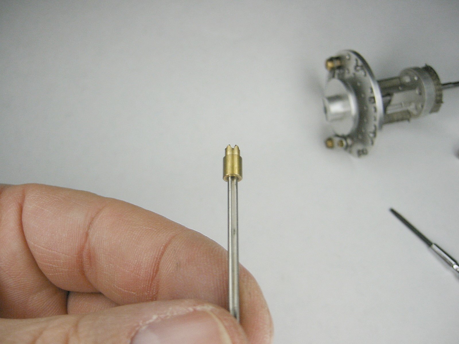
The Setting Shaft |
The Setting Shaft |
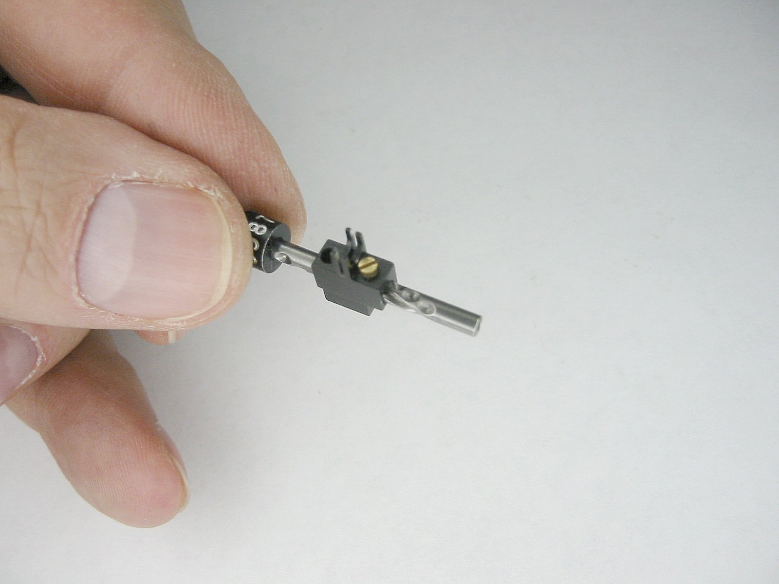
The Setting Shaft |
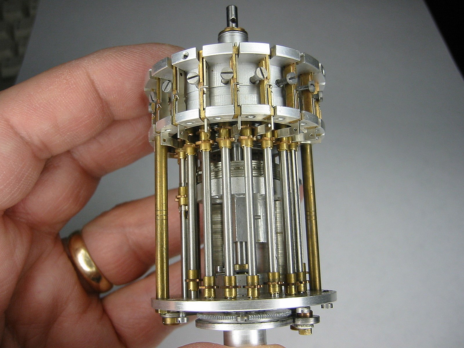
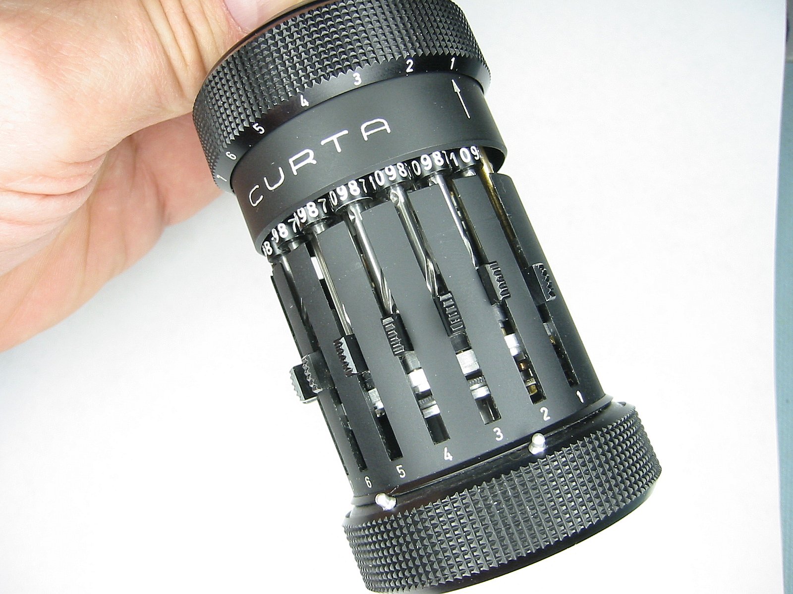
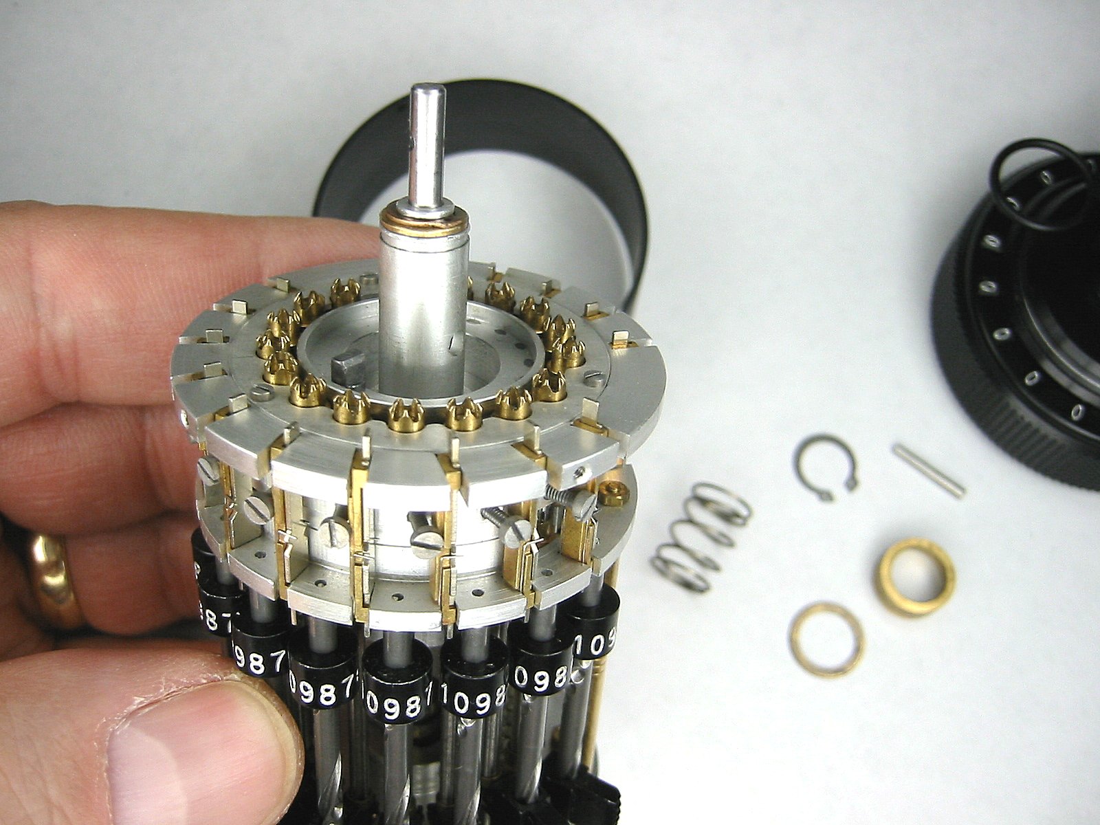
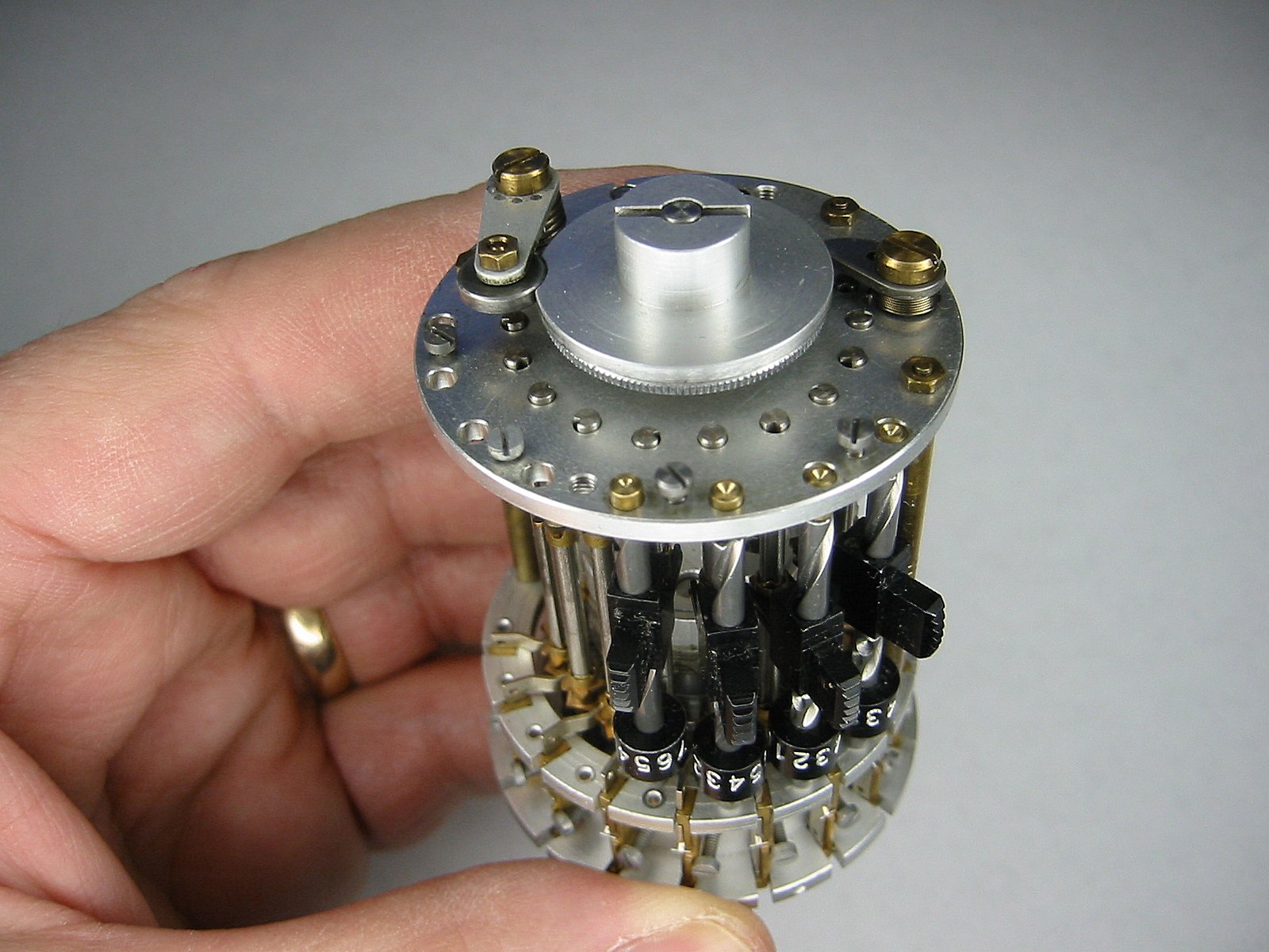
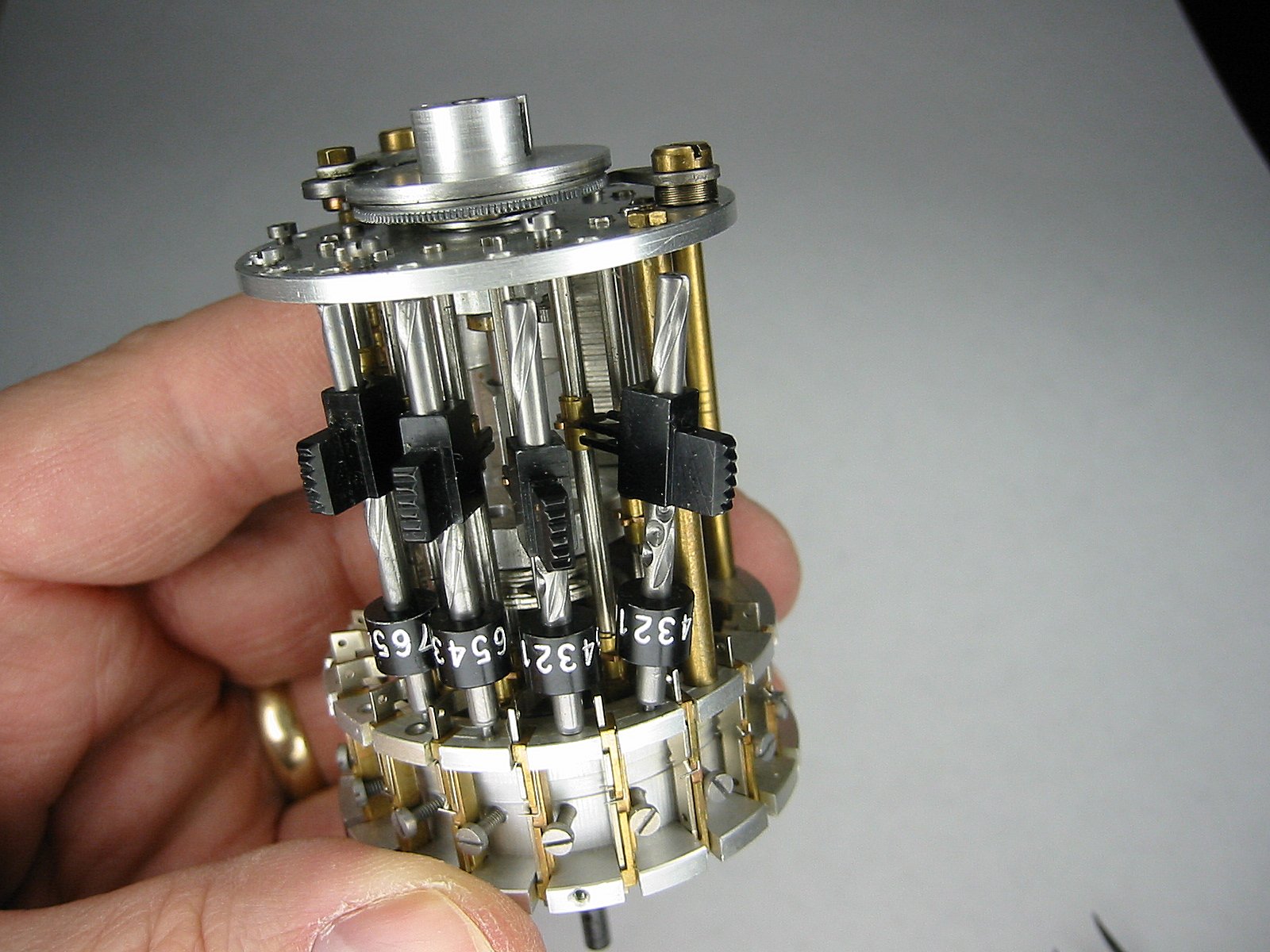
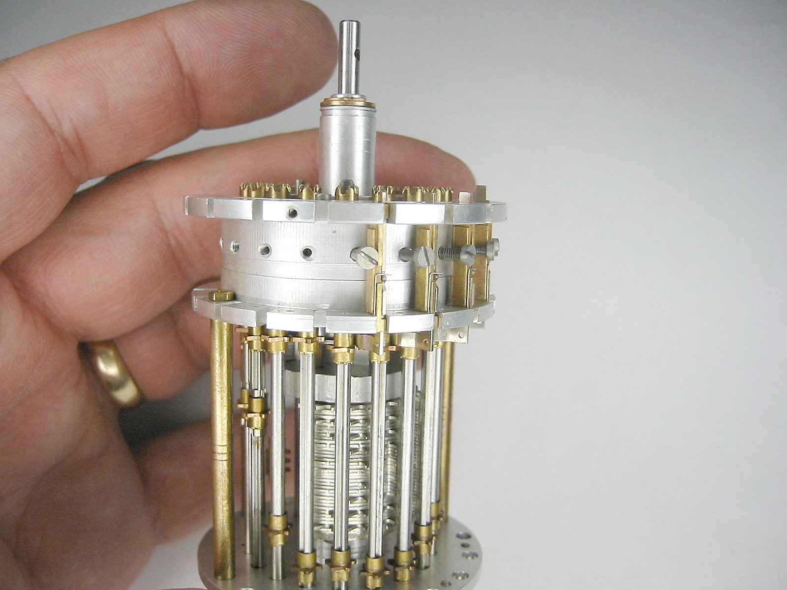
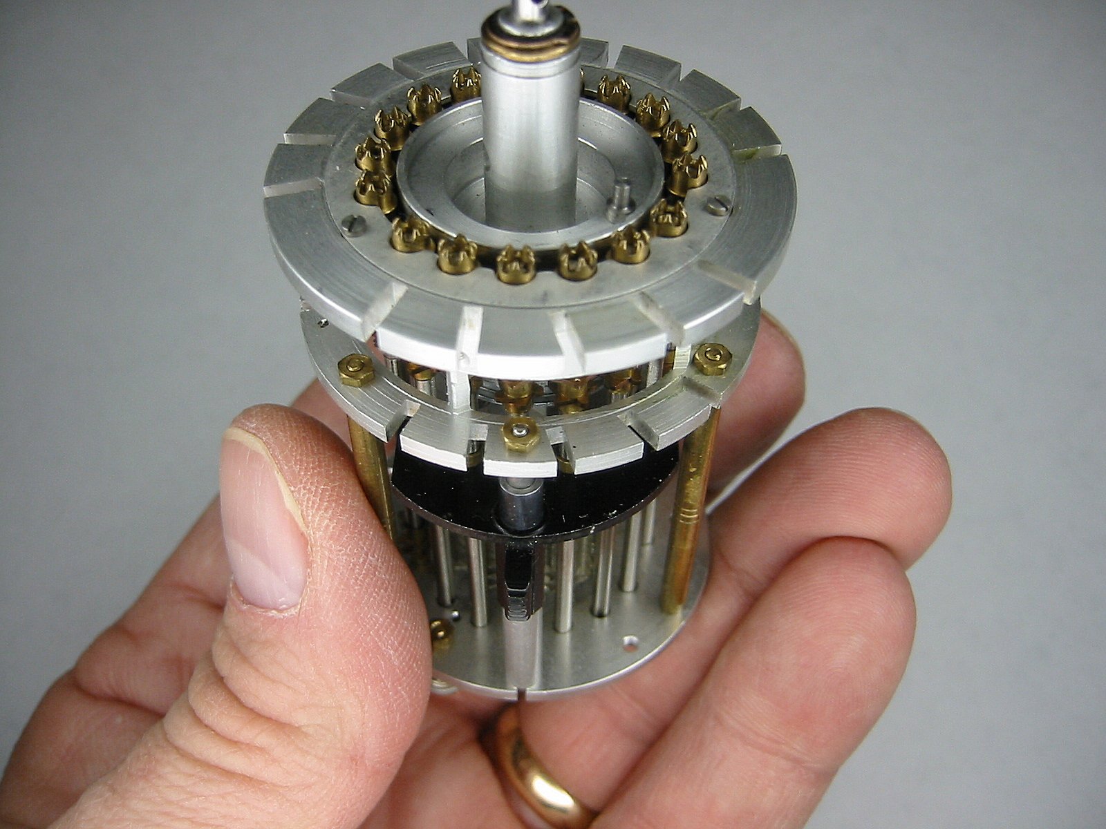
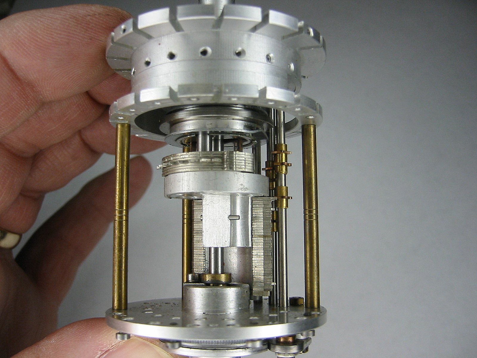
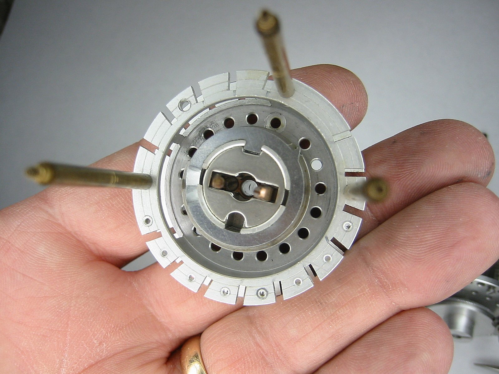
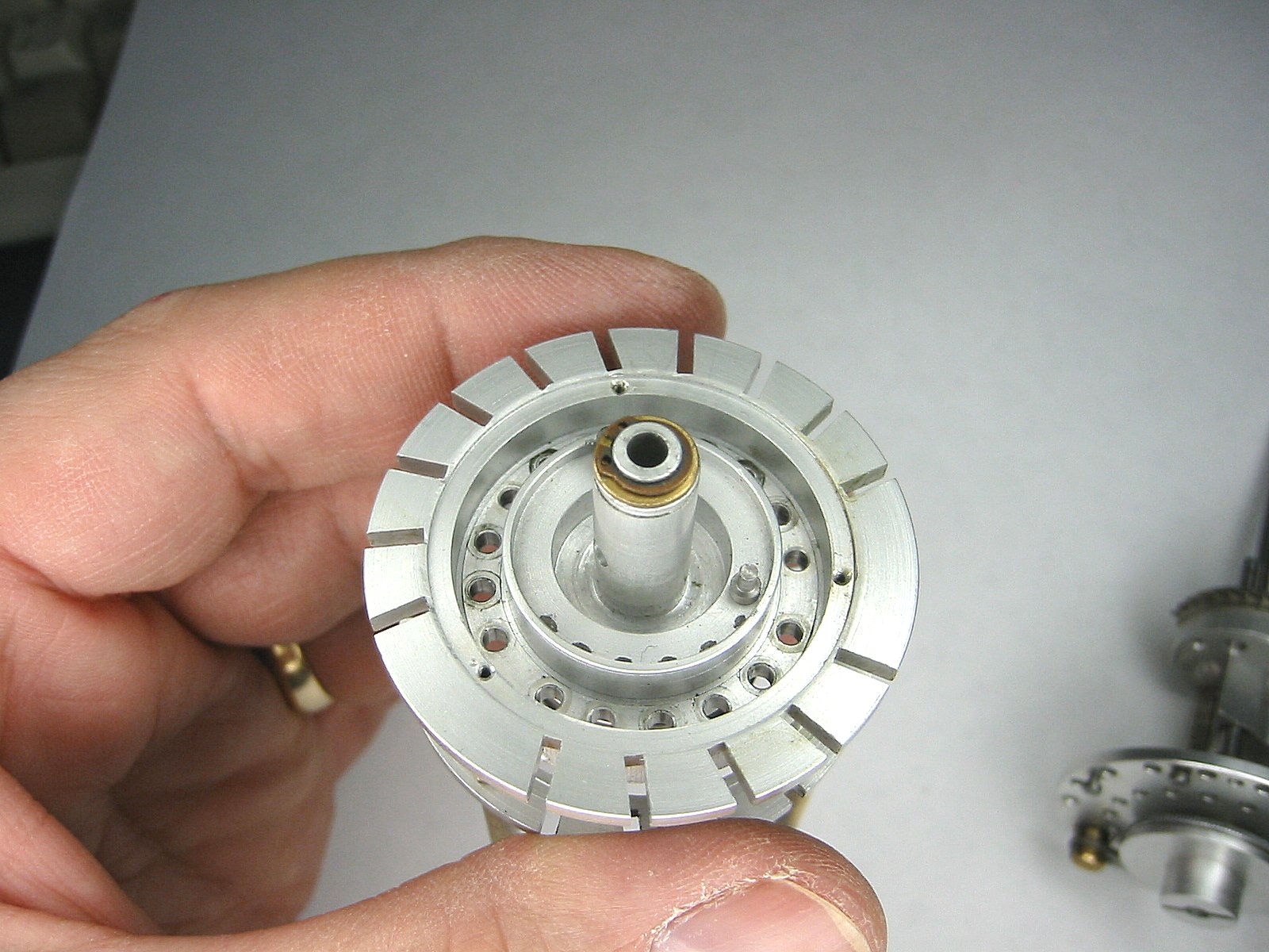
Now you can begin to see the inner workings of the Curta more clearly. |
The inner workings |
Now we're going to up the difficulty another notch. Don't try this unless you have exceptional mechanical dexterity. We're going to remove all of the ten carry bearings. Remove the screw to the left of the ten carry assembly. Then gently pull the entire assembly straight out. This is easy... getting it back in on re-assembly is the hard part! |
The ten carry bearings removal |
The ten carry bearings removal |
The ten carry bearings removal |
It's bare! No ten carry bearings! |
It's bare! No ten carry bearings! |
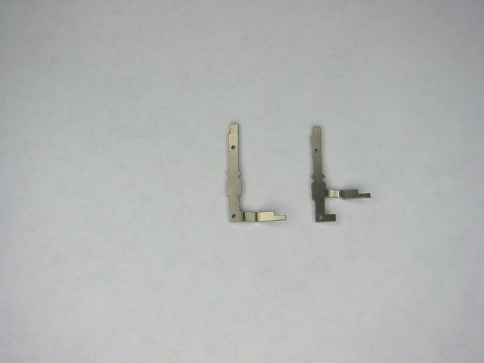
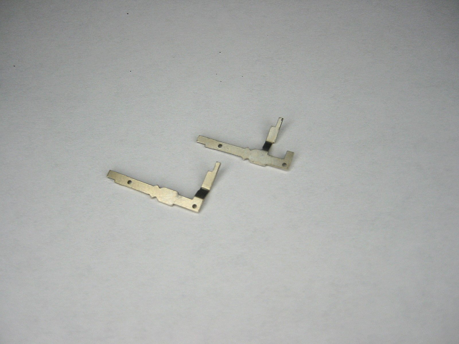
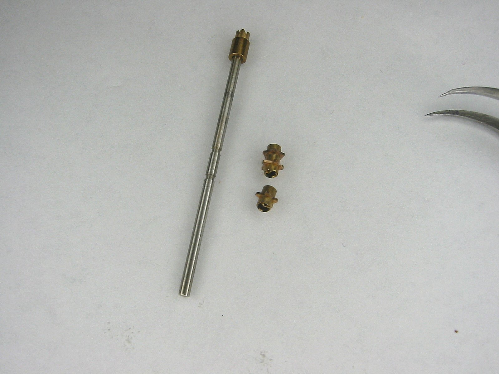
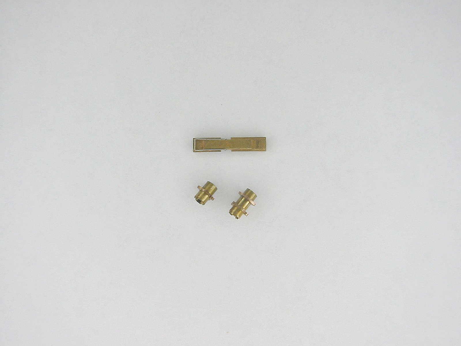
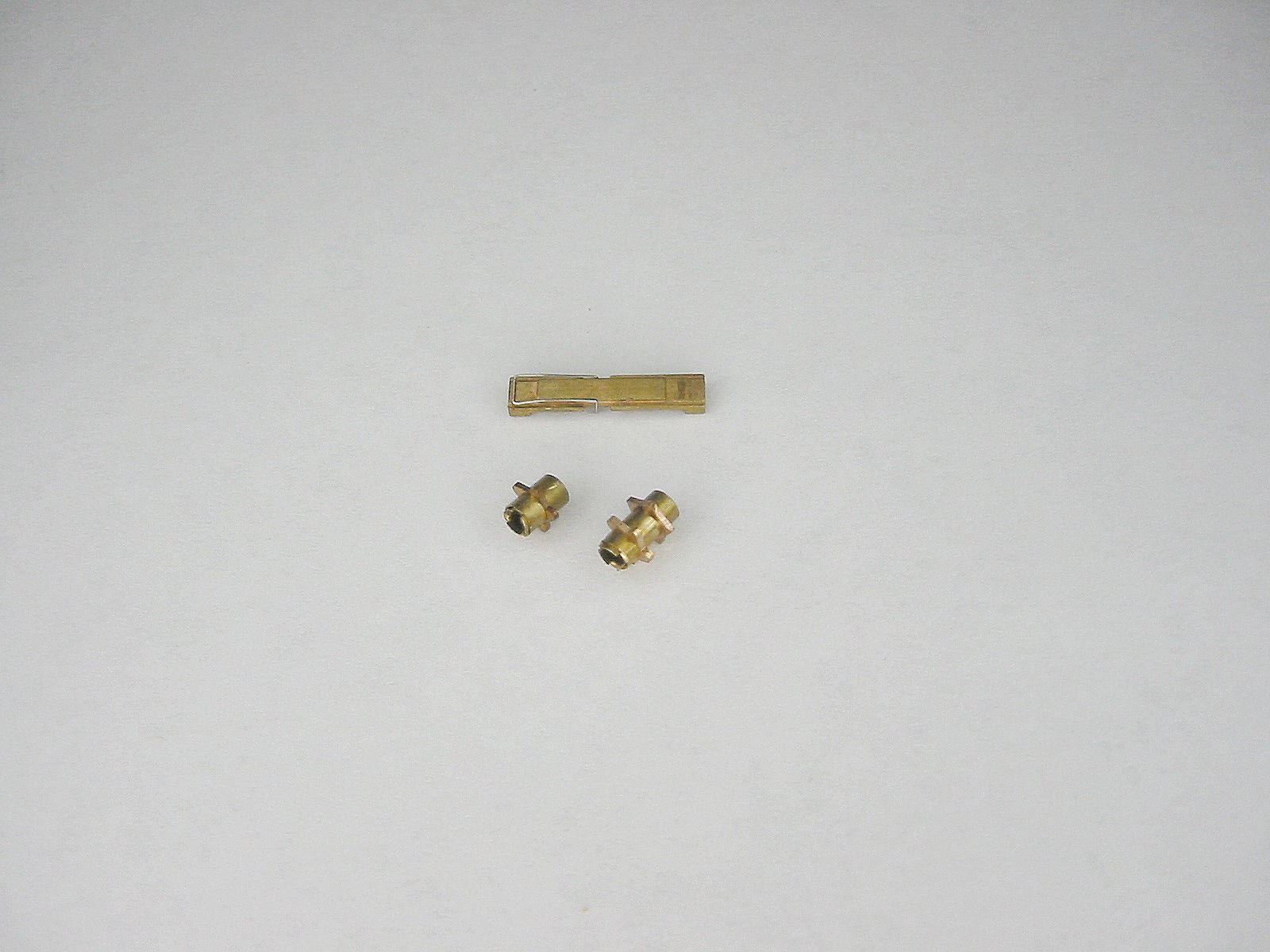
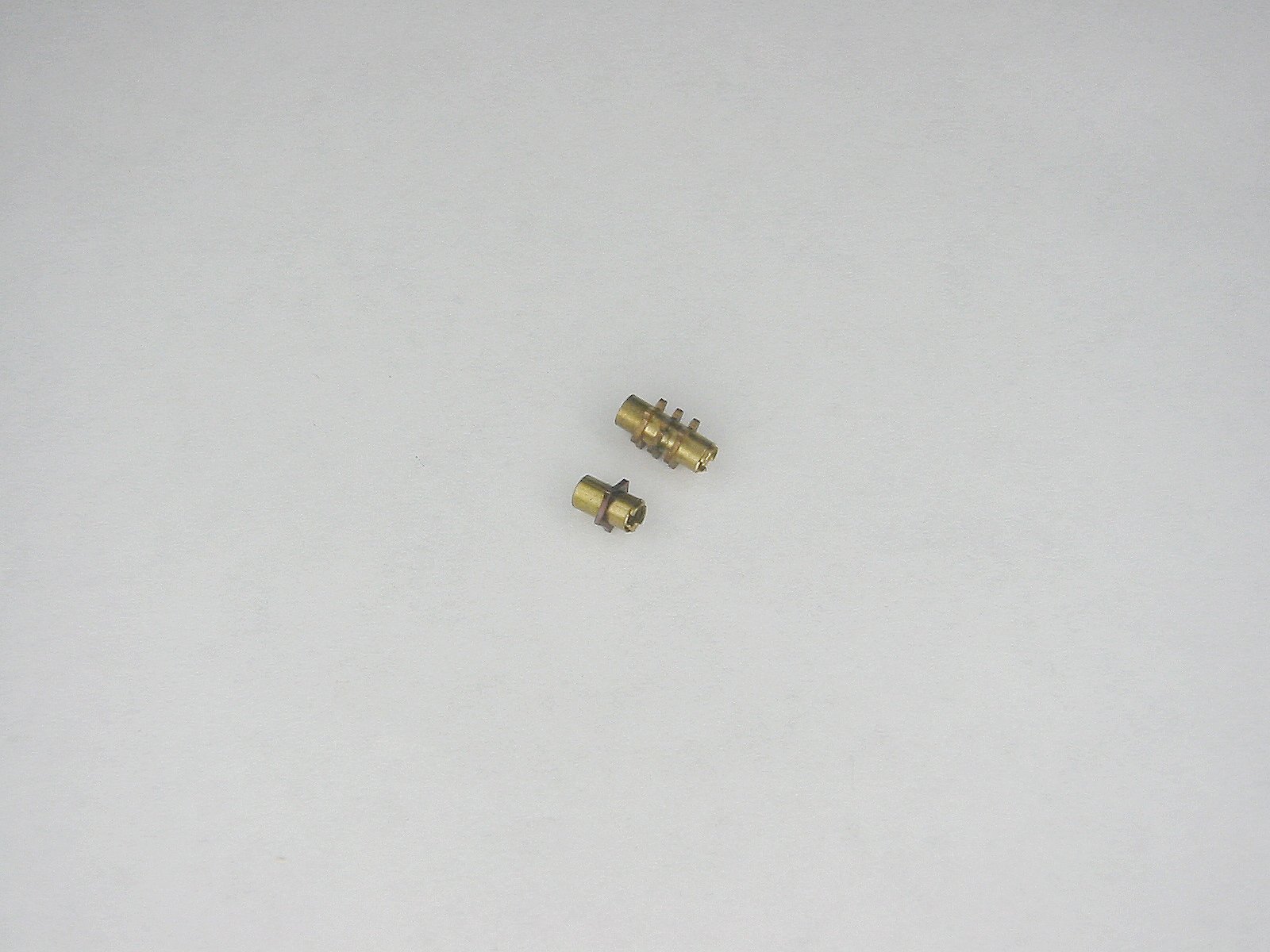
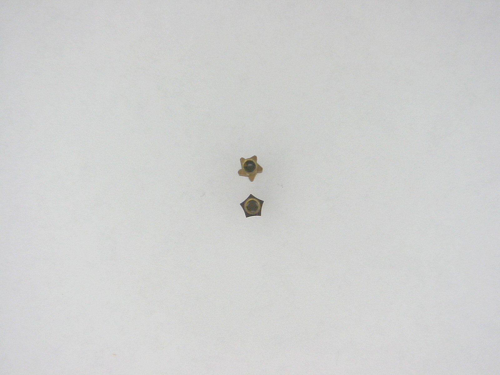
Here are the ten carry shafts. There are two types. The one on the left works with the main accumulator. The right on works with the turns counter accumulator. |
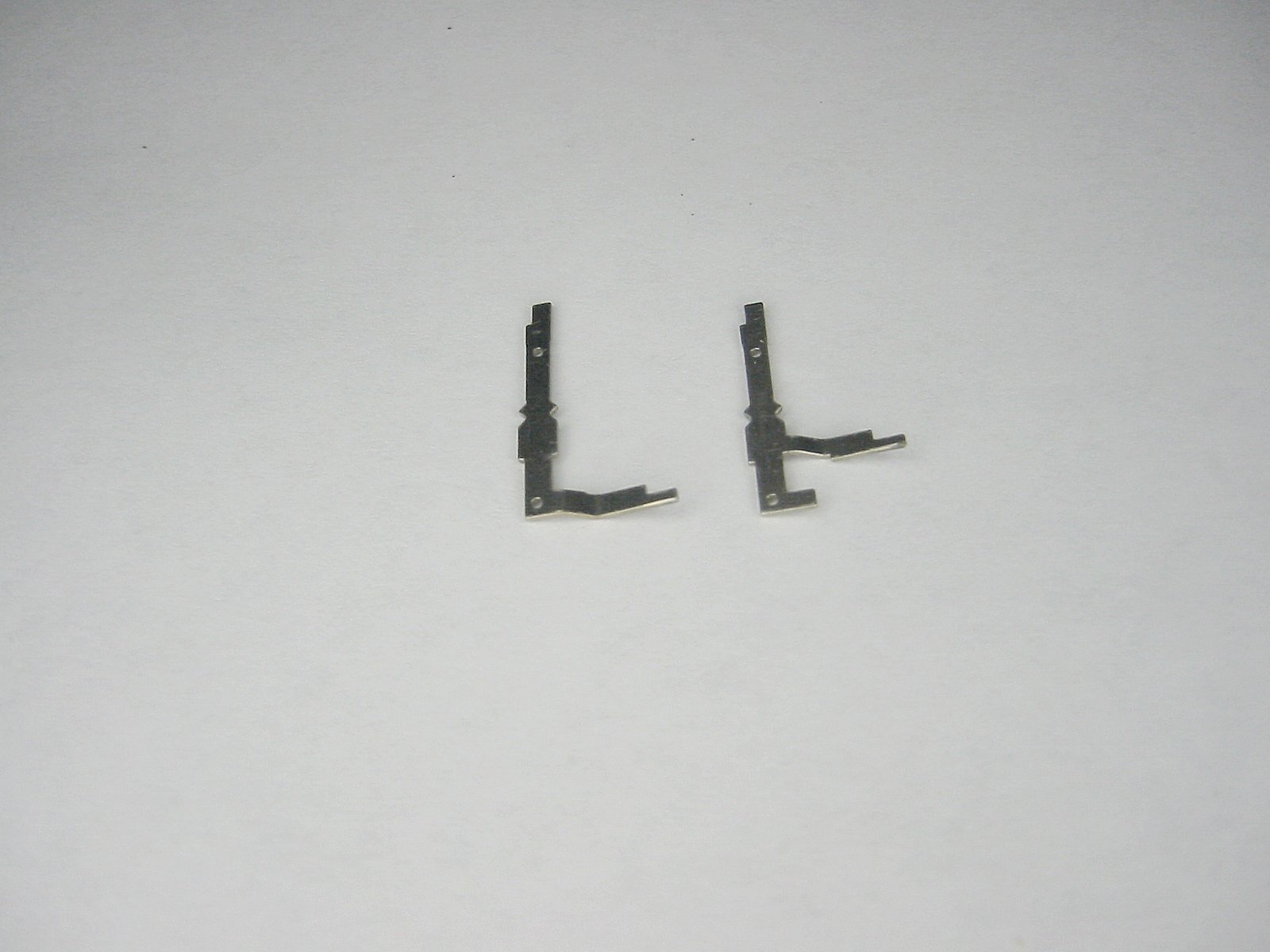
The ten carry shafts |
The ten carry shafts |
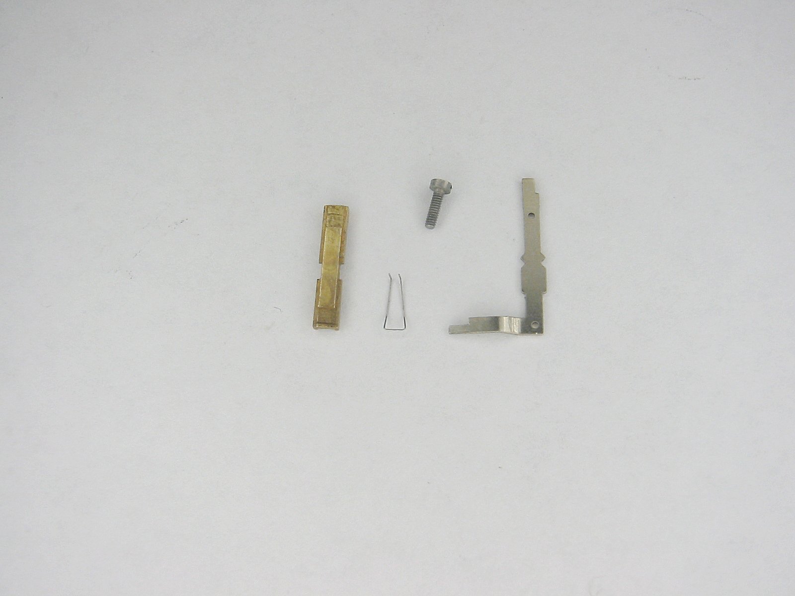
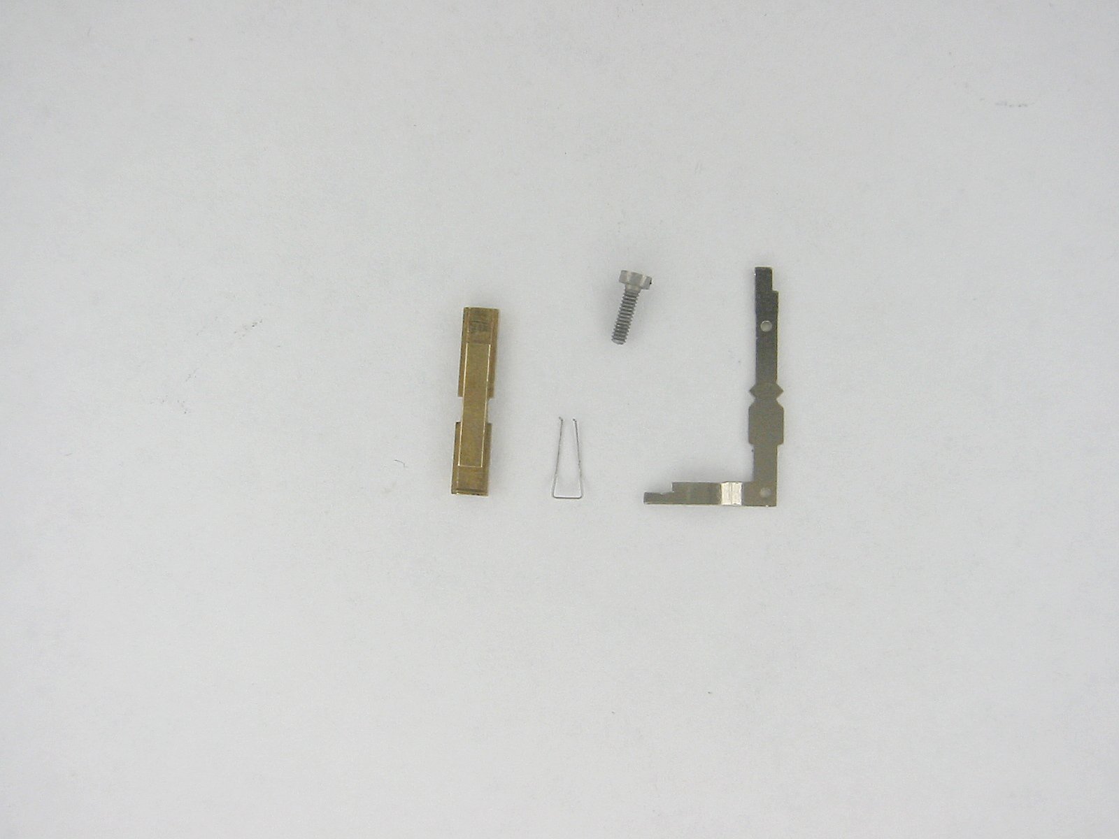
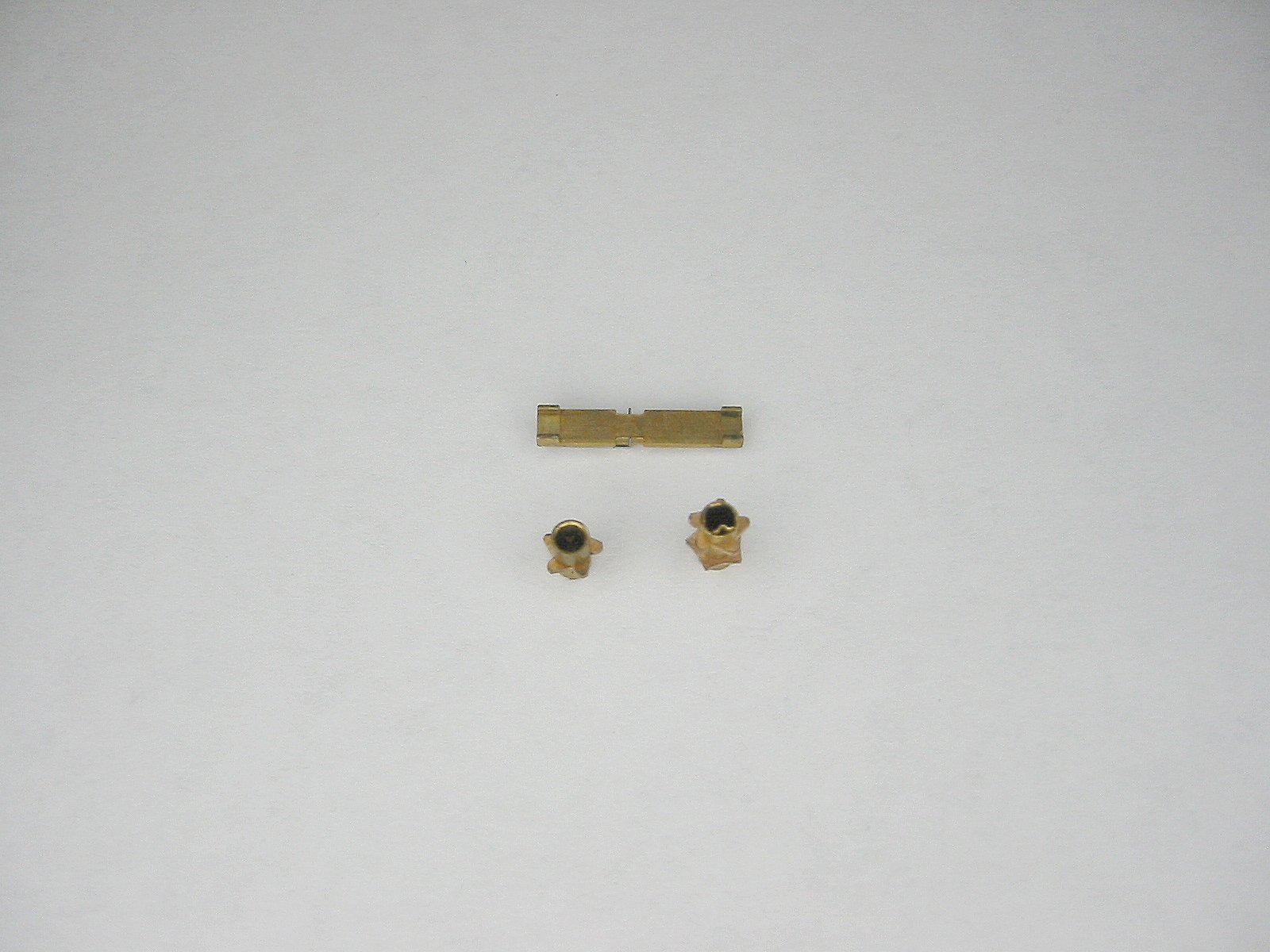
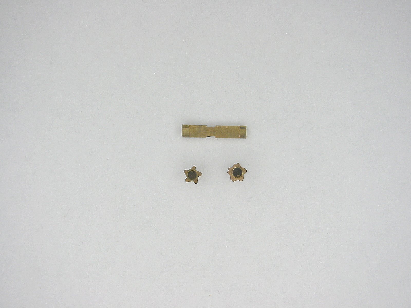
Here are all of the tens carry assembly parts. From left to right, the ten carry lever bearing block, the ten carry spring, the ten carry screw, and the ten carry lever. |
The ten carry shafts |
The ten carry shafts |
Now we're going to remove the Reversing lever. |
Now we're going to remove the Reversing lever. |
Remove the brass nut holding the top of the Reversing lever shaft. |
Slide the Reversing shaft down until the slotted portion of the shaft slide through the bottom base. |
And it's out! |
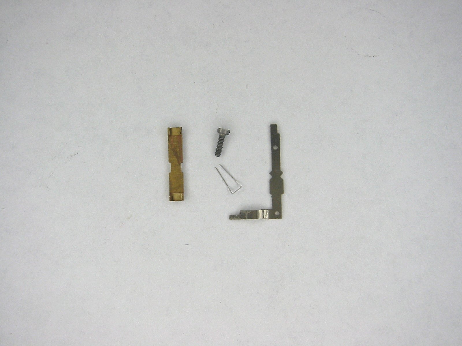
The Reversing lever & shaft |
The Reversing lever & shaft |
The Reversing lever has a short black top spacer and longer lower spacer. |
As before, don't remove the Reversing lever knob from the shaft. It contains a tiny spring and ball bearing just like the Setting shafts. |
The Reversing lever & shaft |
The Reversing lever & shaft |
The Reversing lever & shaft |
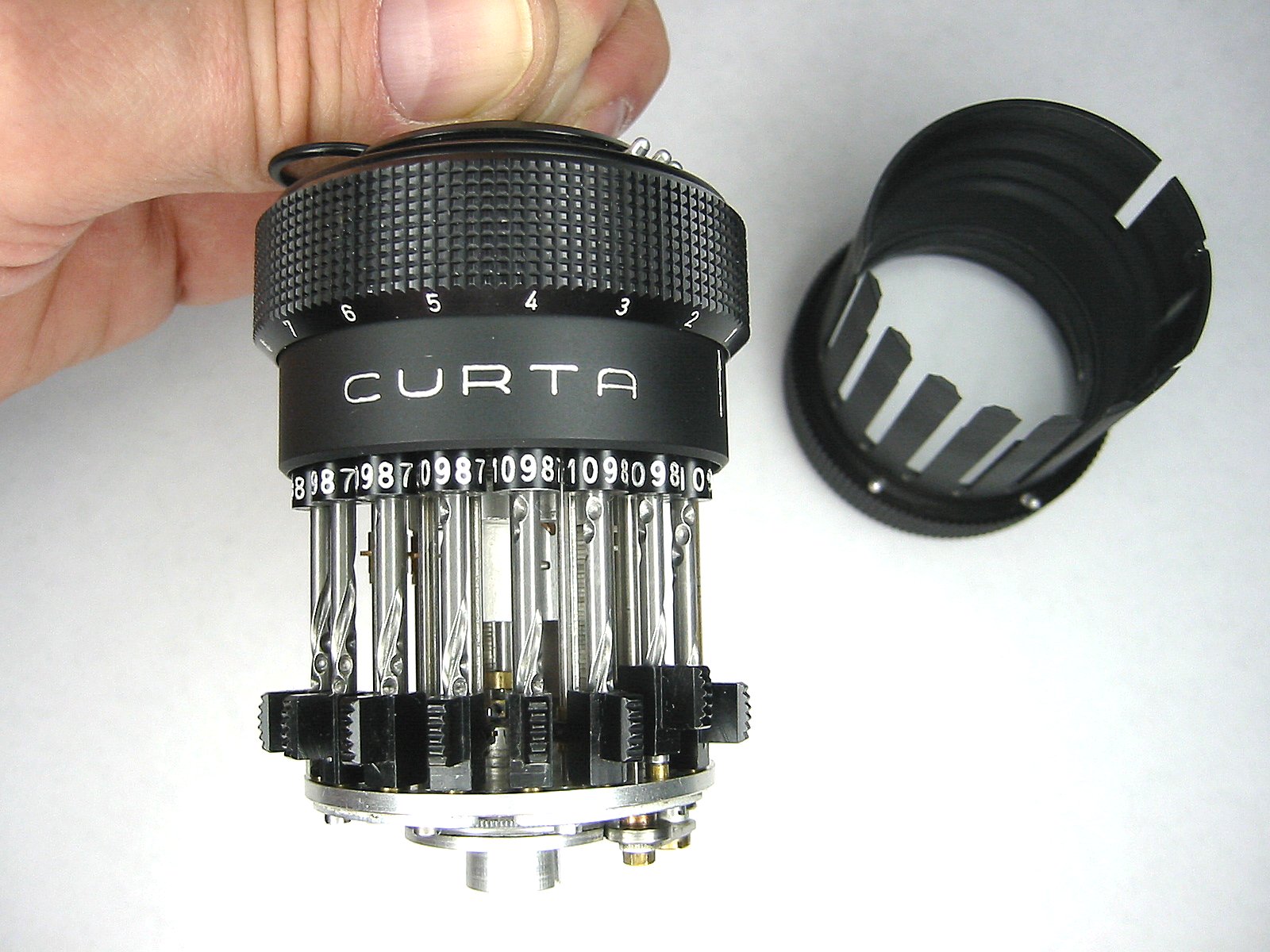
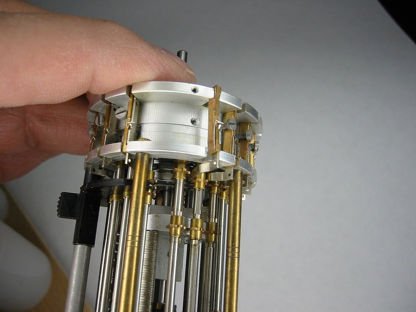
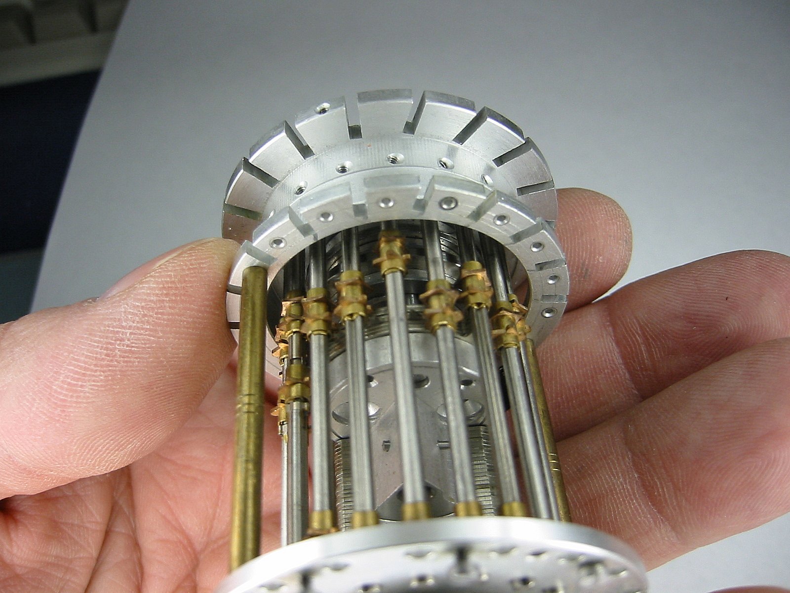
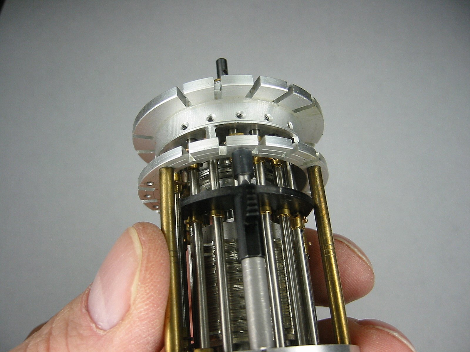
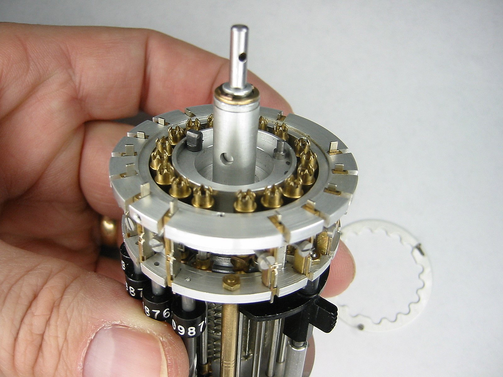
Now remove the three screws that hold the Locking ring onto the top of the Curta. Keep the Curta upright so the transmission shafts do not fall out. |
The Locking ring |
The Locking ring |
The Locking ring |
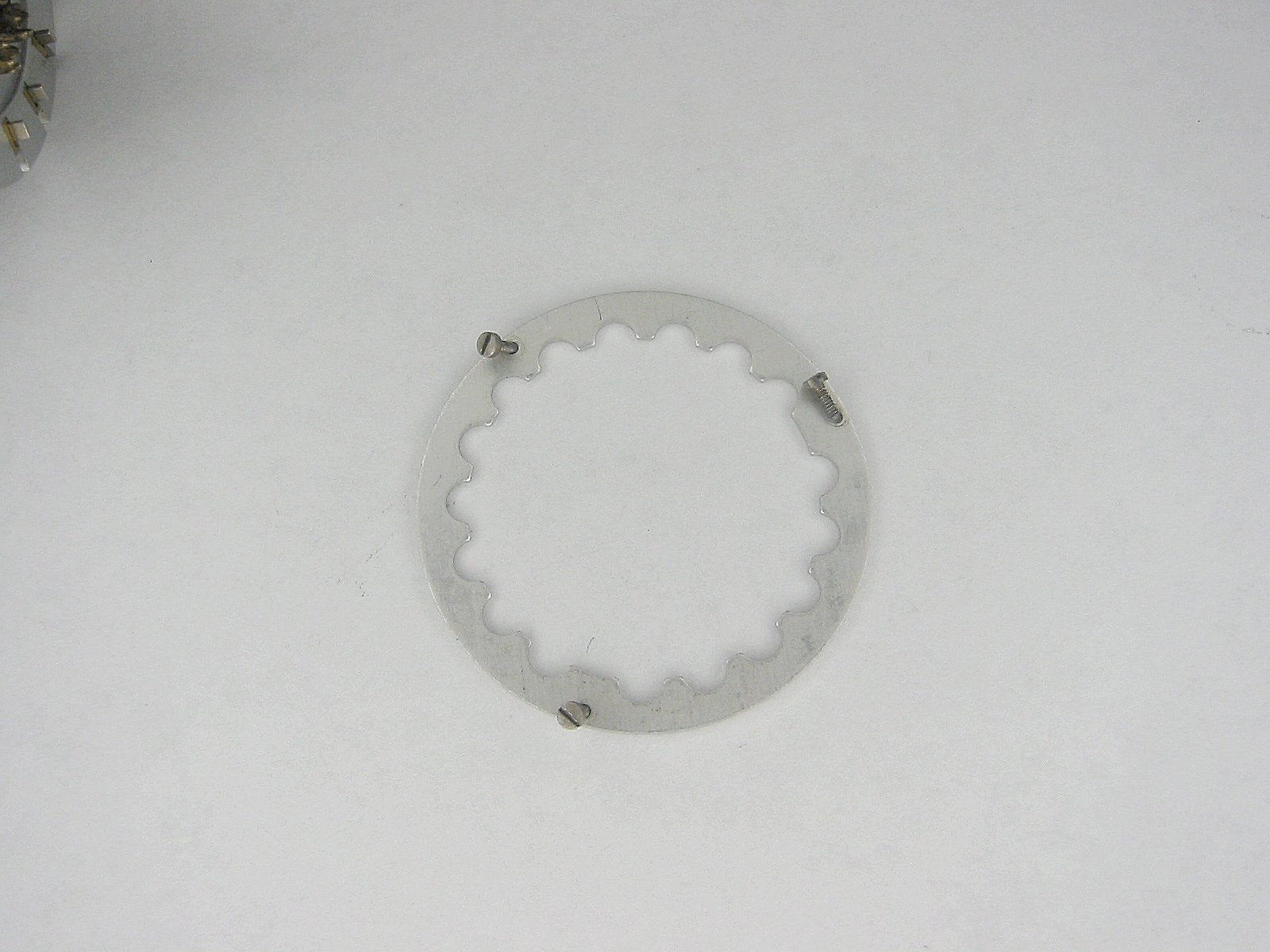
Here's the top Locking ring and it's three screws. |
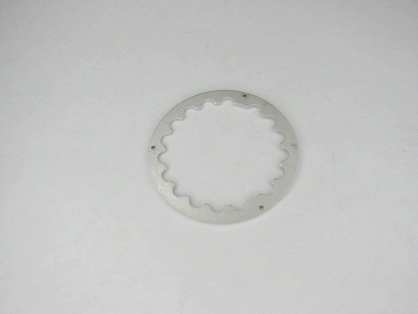
The Locking ring |
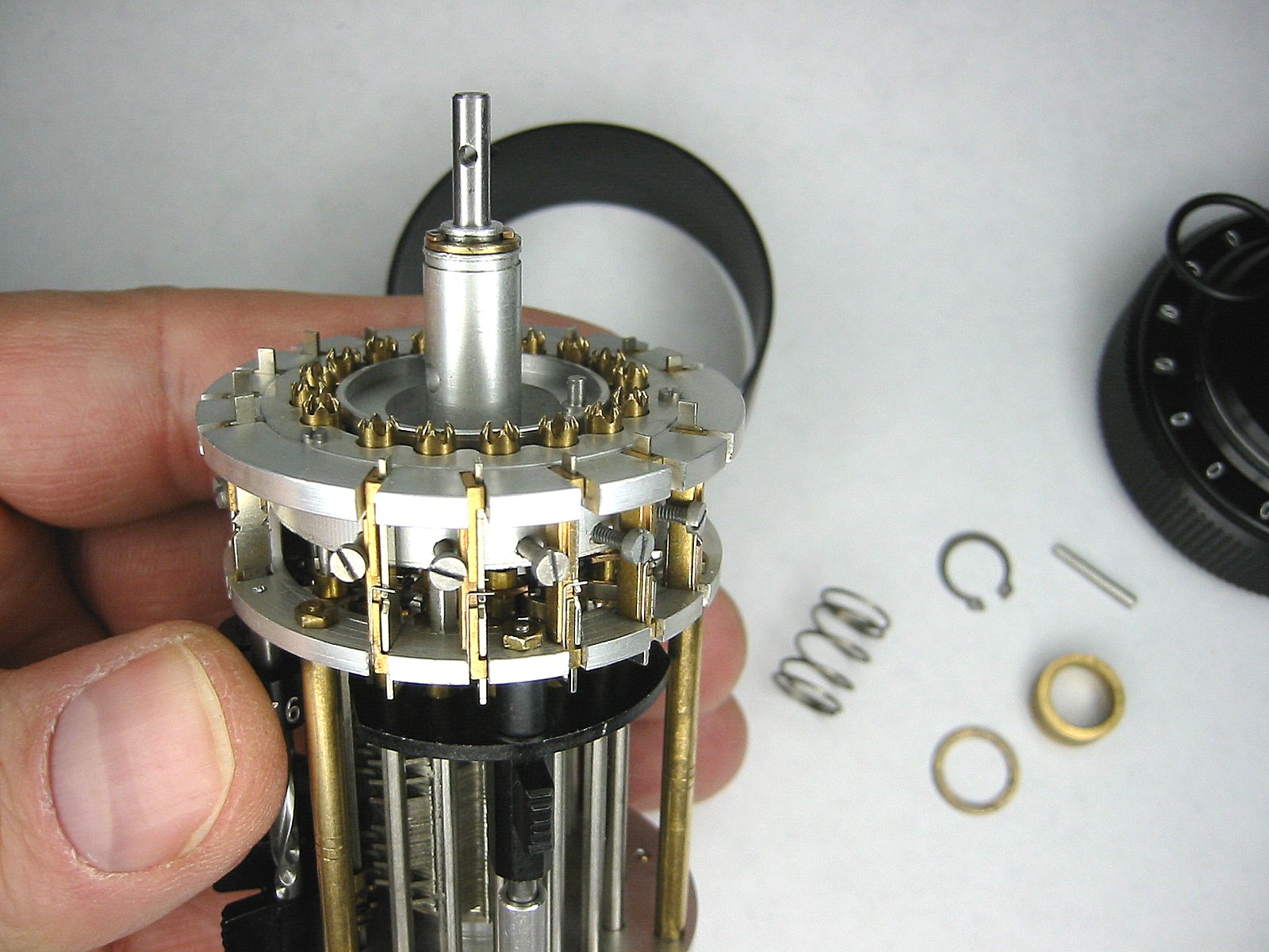
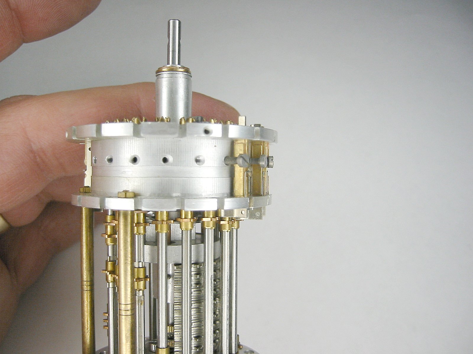
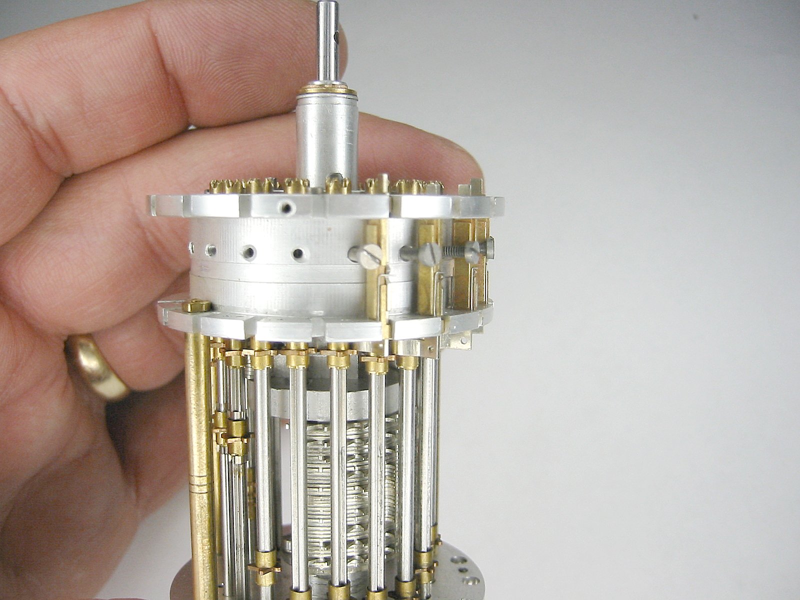
Now we're going to up the difficulty lever one more notch. Don't proceed unless you're really good with precision tweezers and tiny-tiny c-clips! 5 of the 17 shafts have a total of 9 c-clips securing some of the transmission gears in place. Remove all of these c-clips. Push the first shaft up and slide the transmission gears off of the bottom. |
The transmission shafts |
The transmission shafts |
Here's the top of the transmission shaft. |
The transmission shafts & gears |
Here's the transmission shaft and two gears. |
The transmission shafts & gears |
Notice the shape of the left gear? That's the Curta logo on the bottom of the machine! |
The transmission shafts & gears |
Here's a single and double gear with a tens carry lever bearing block and spring in the background. |
Here a single and triple gear. There's only 1 triple gear shaft in the Curta and it's in the first position of the turns counter. |
The gear on the bottom is used to prevent the shaft from turning in conjunction with the tens bell (see below). |
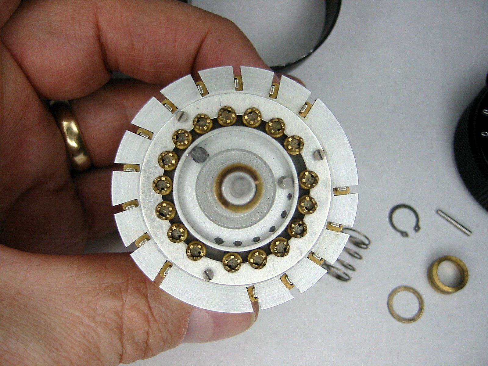
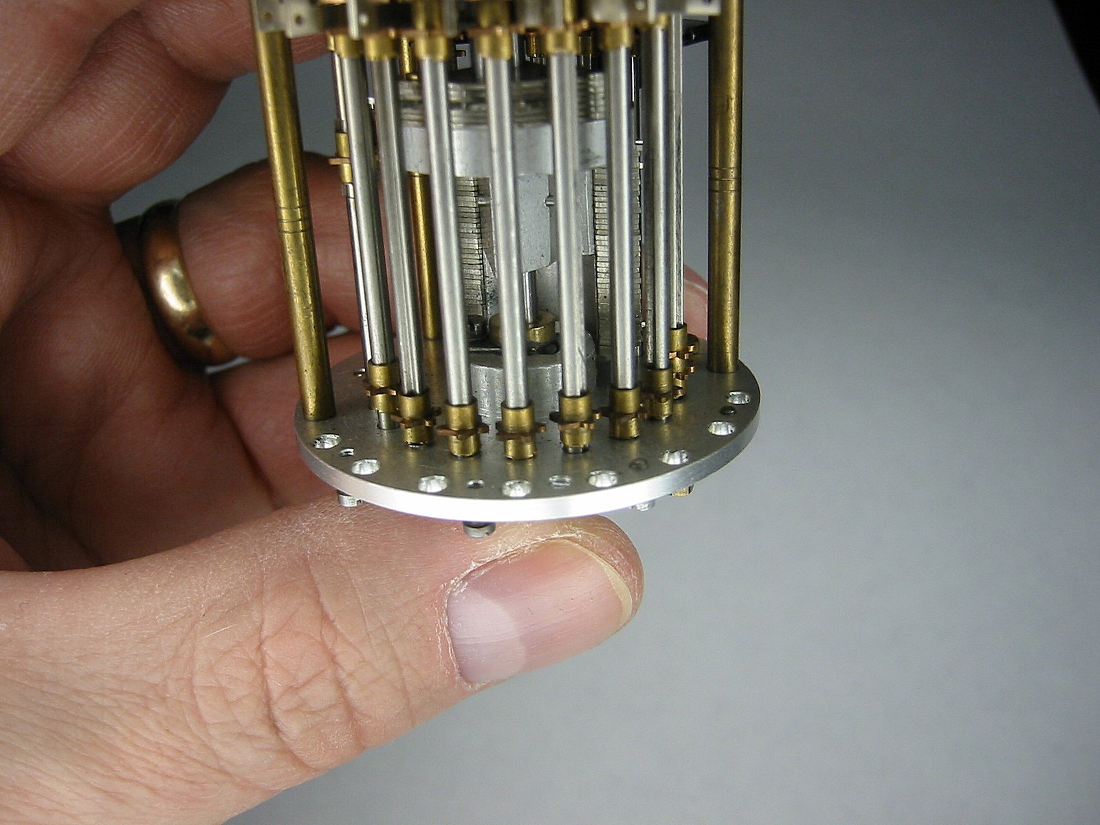
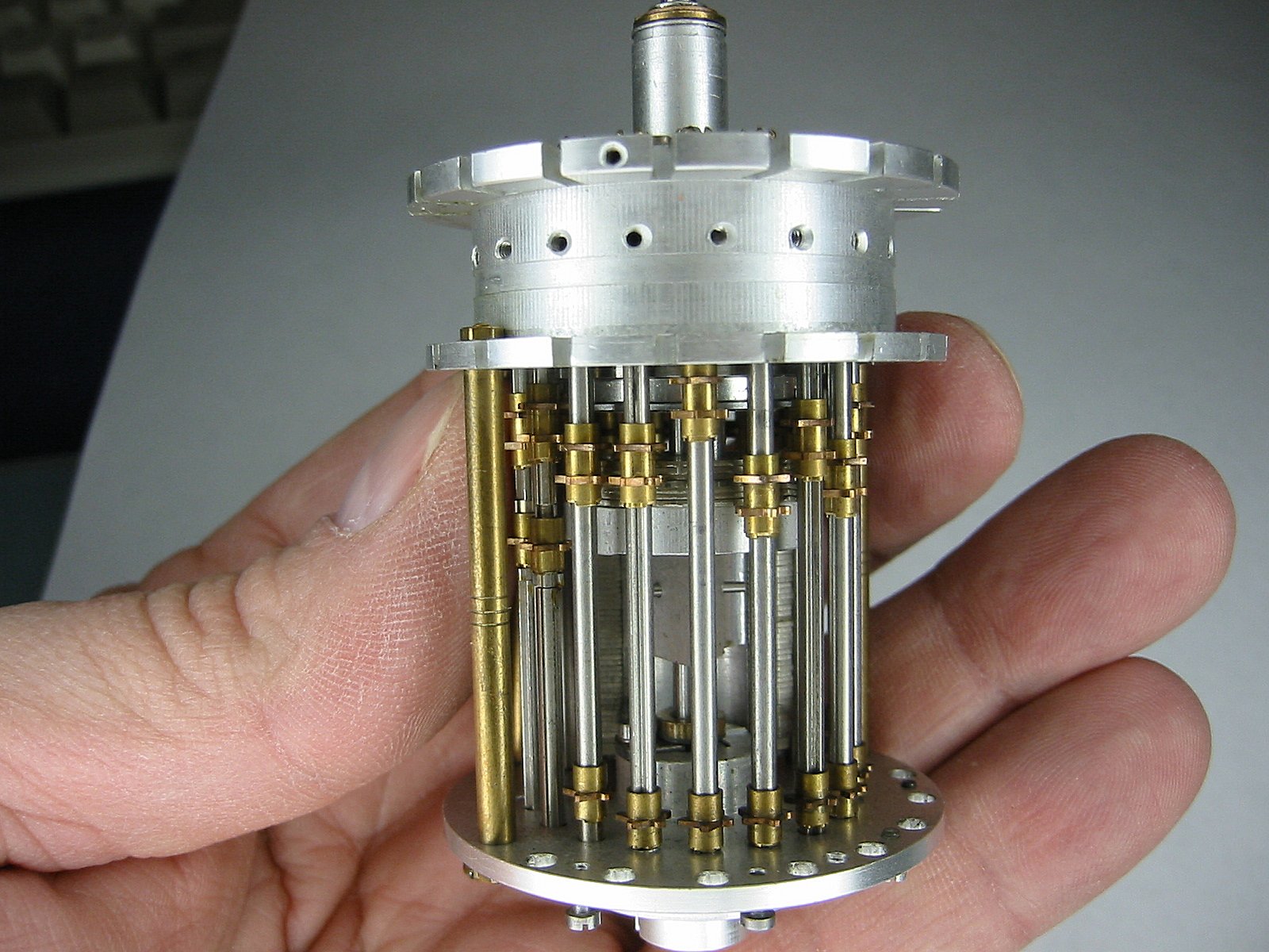
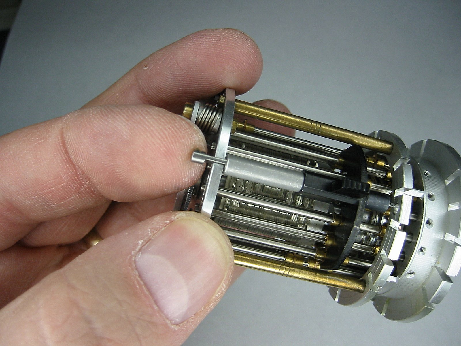
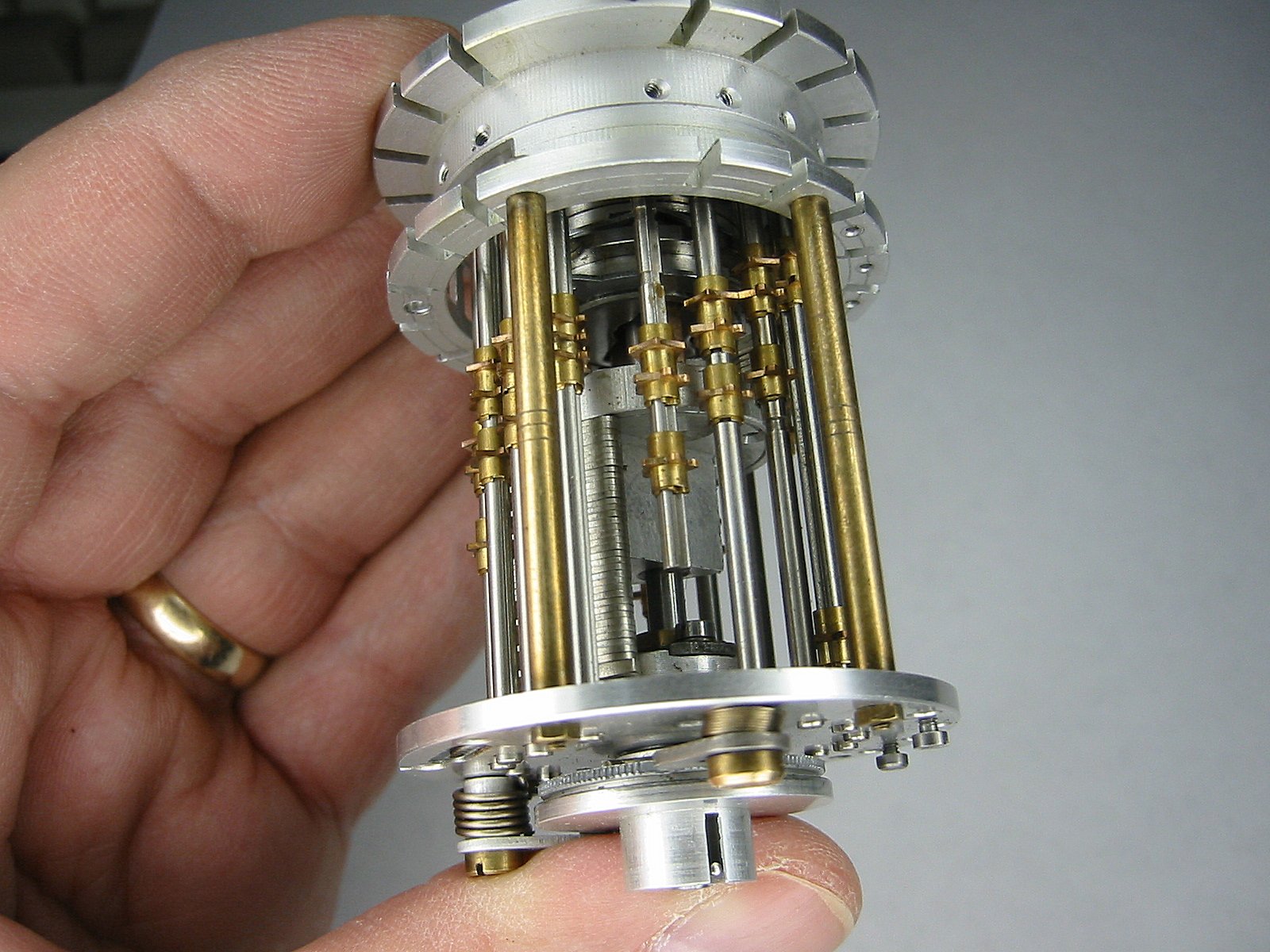
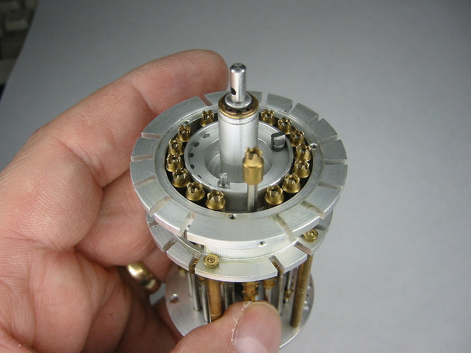
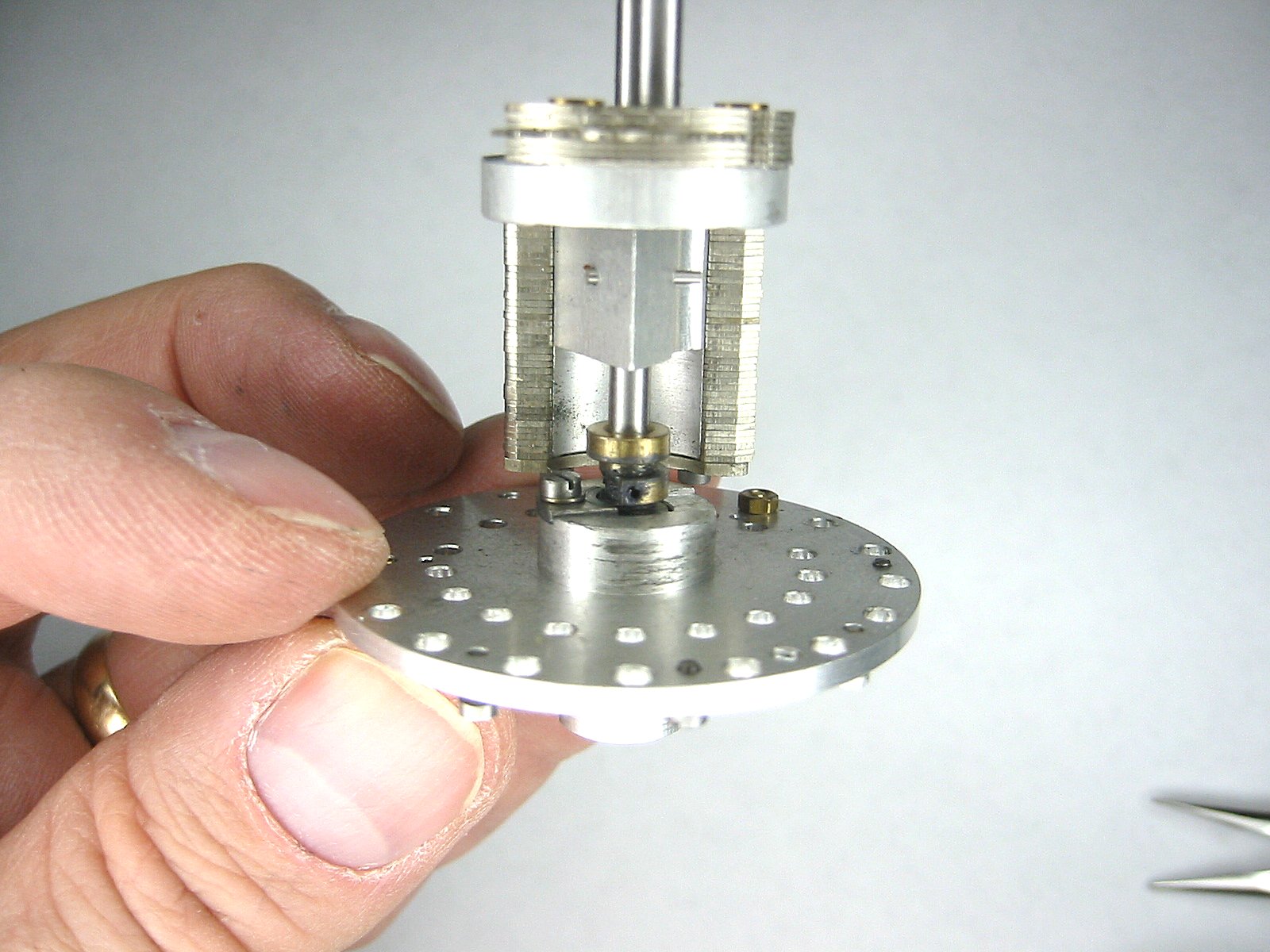
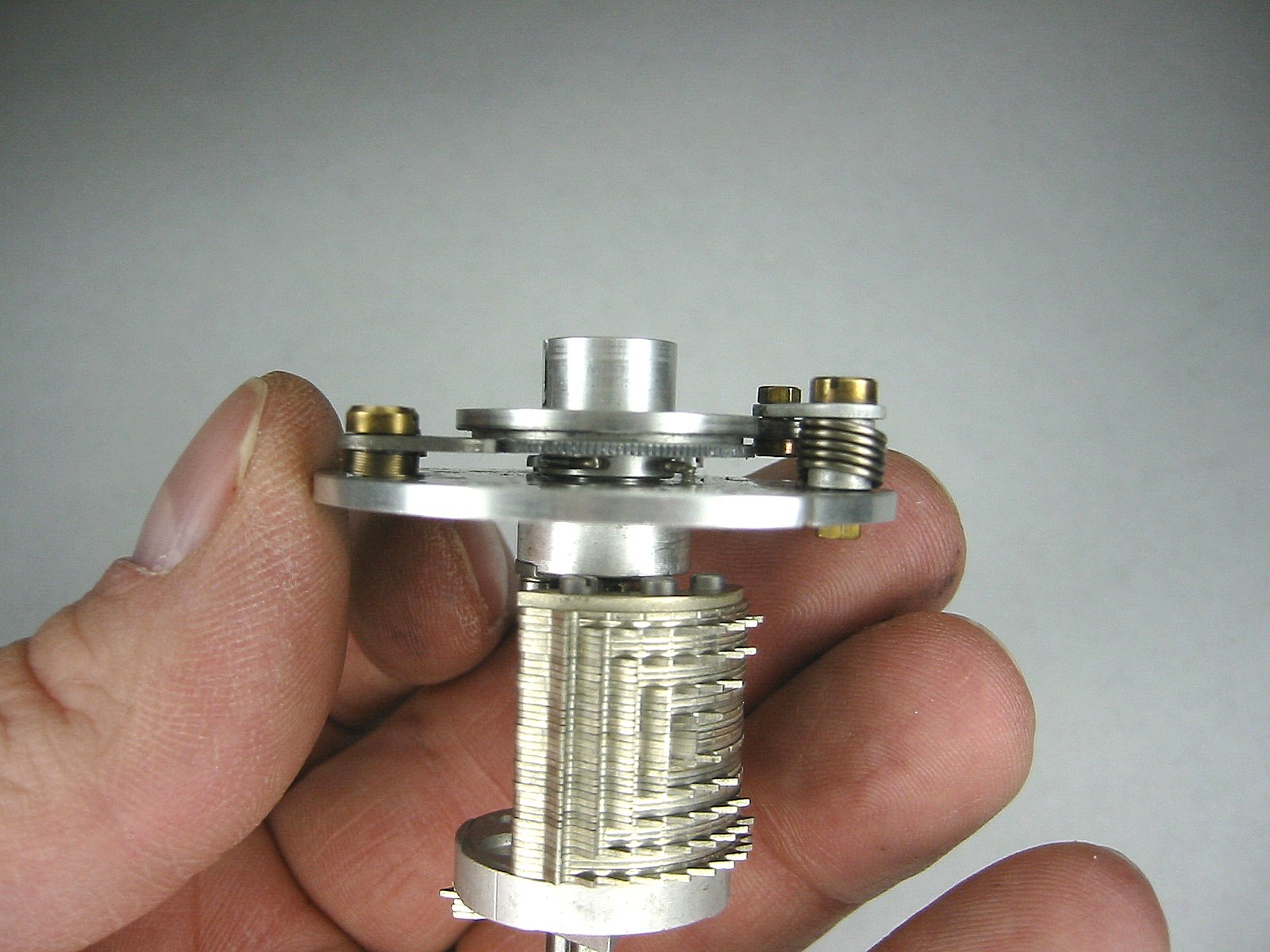
Now it's really bare! |
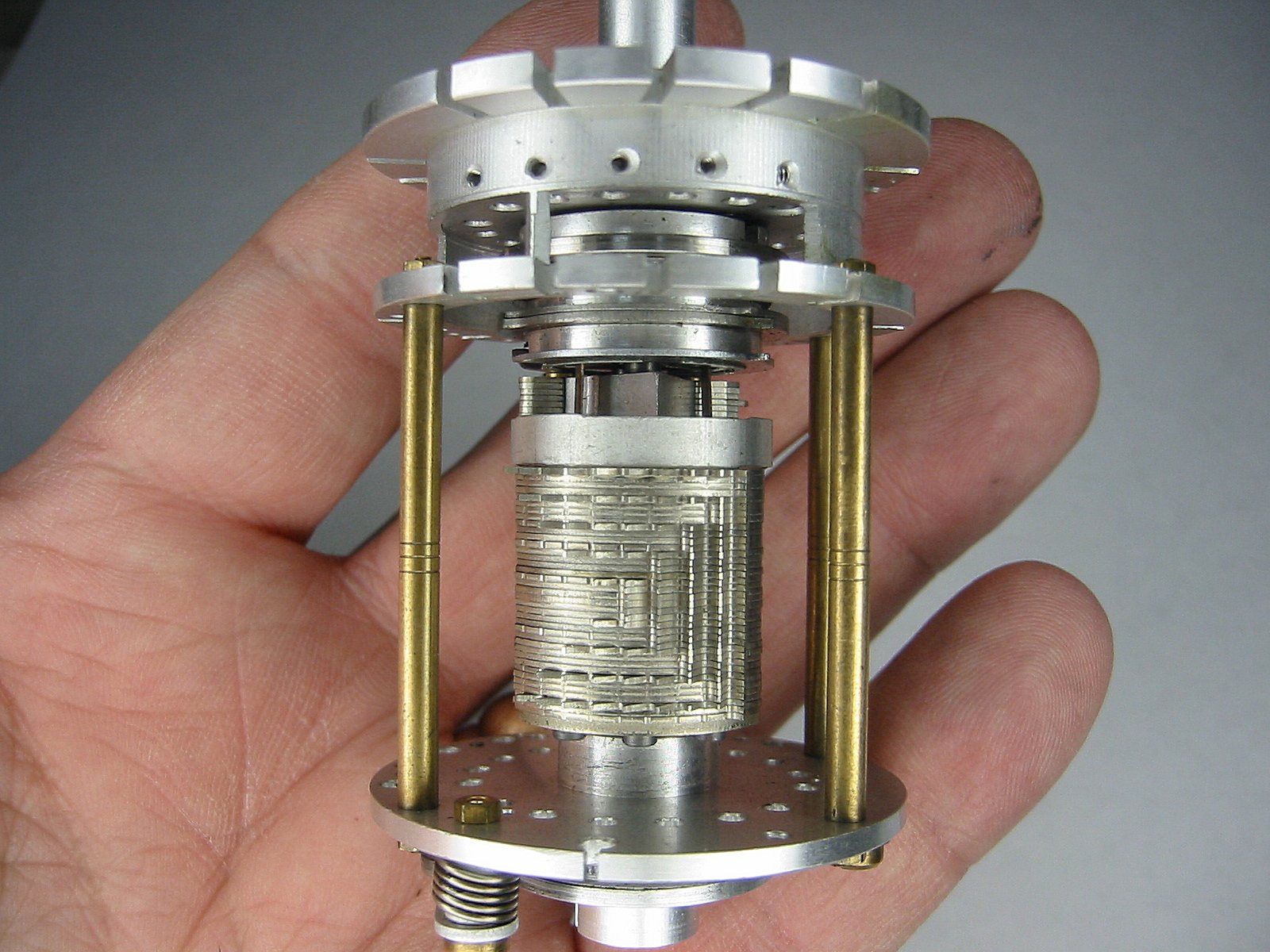
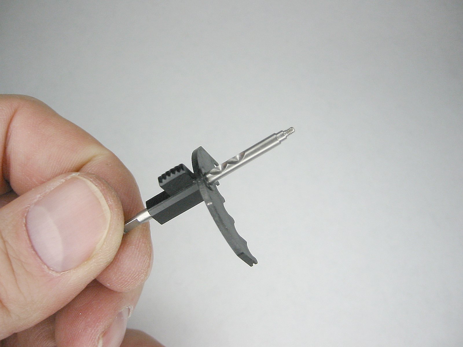
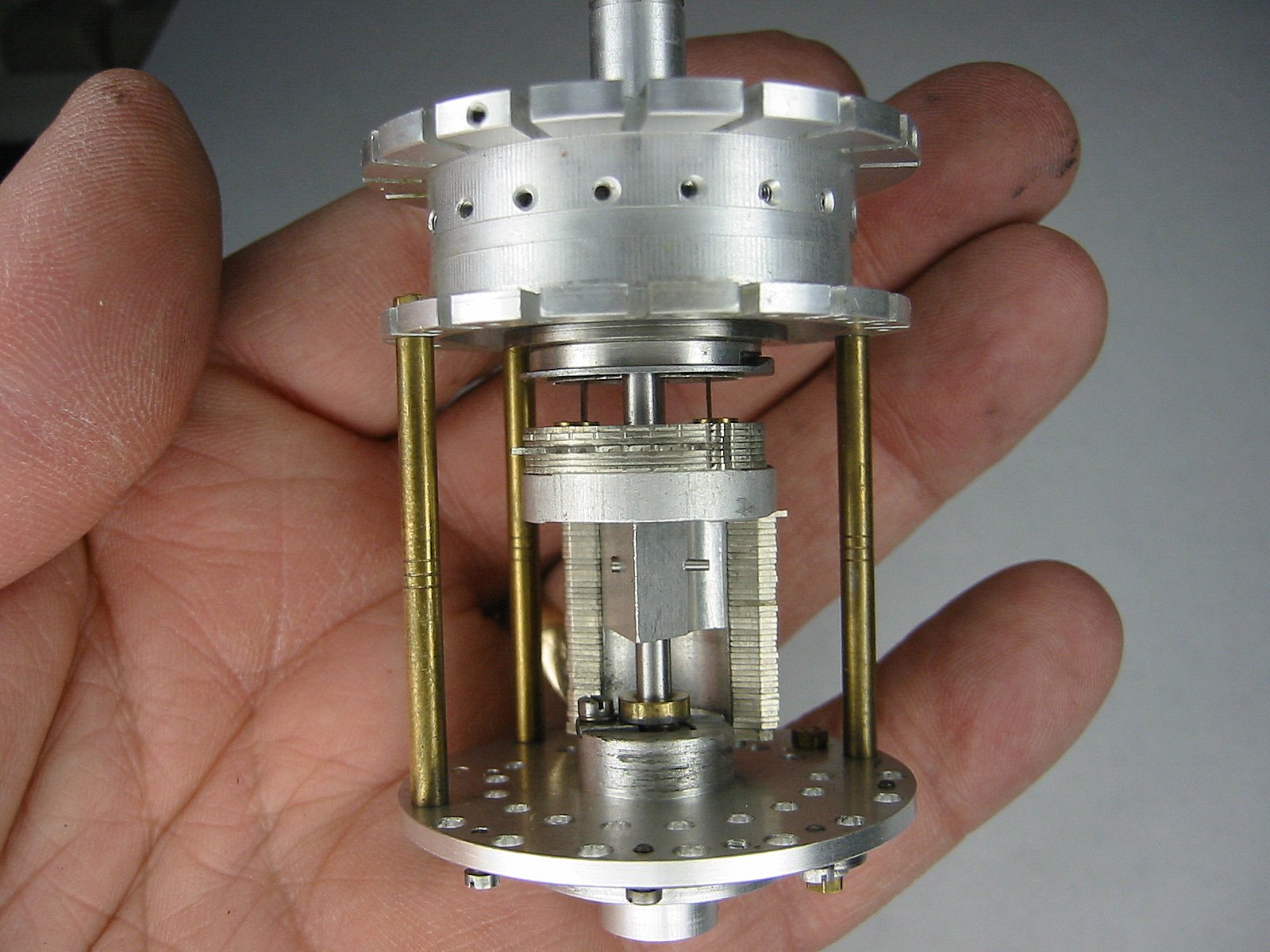
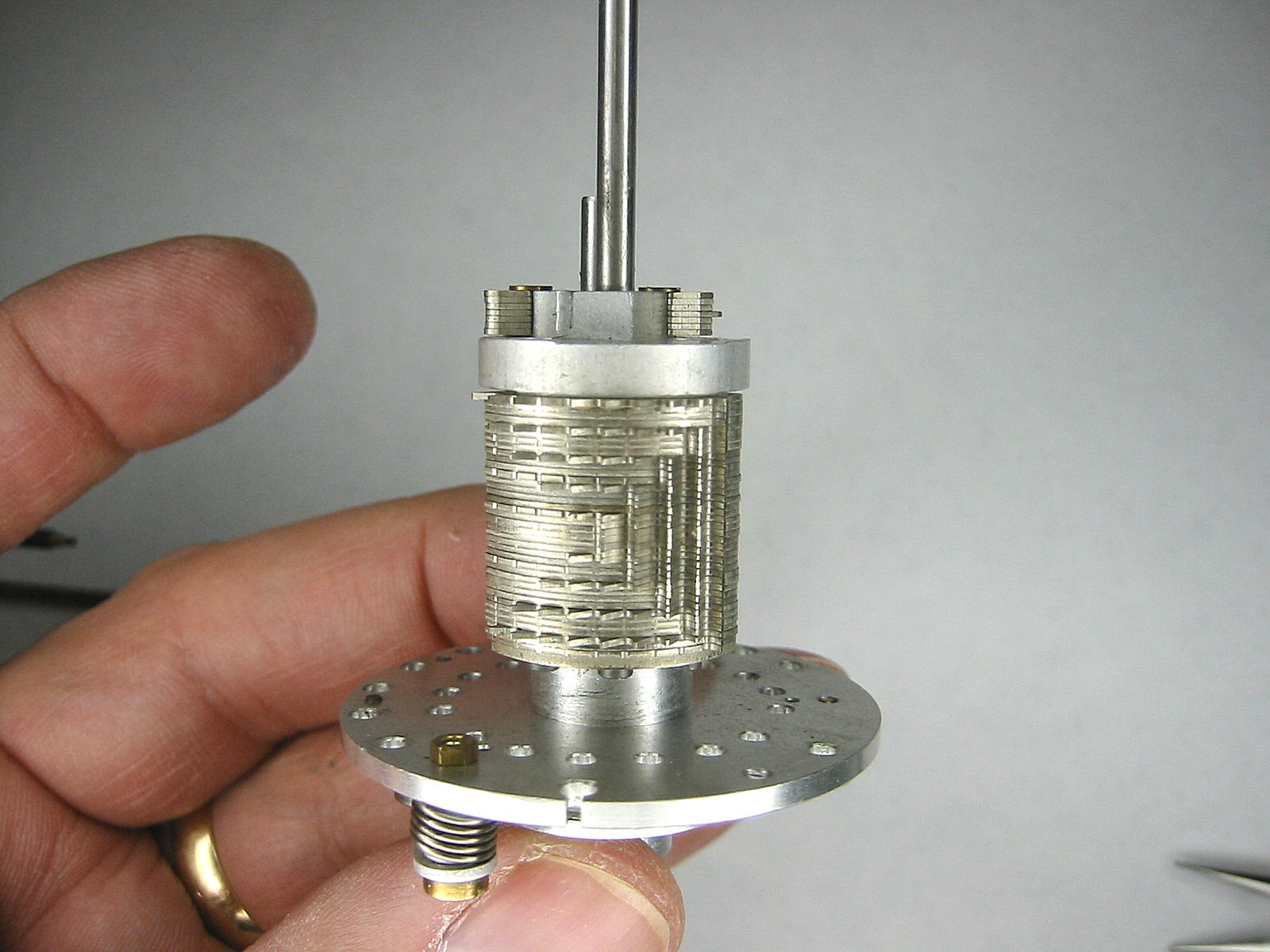
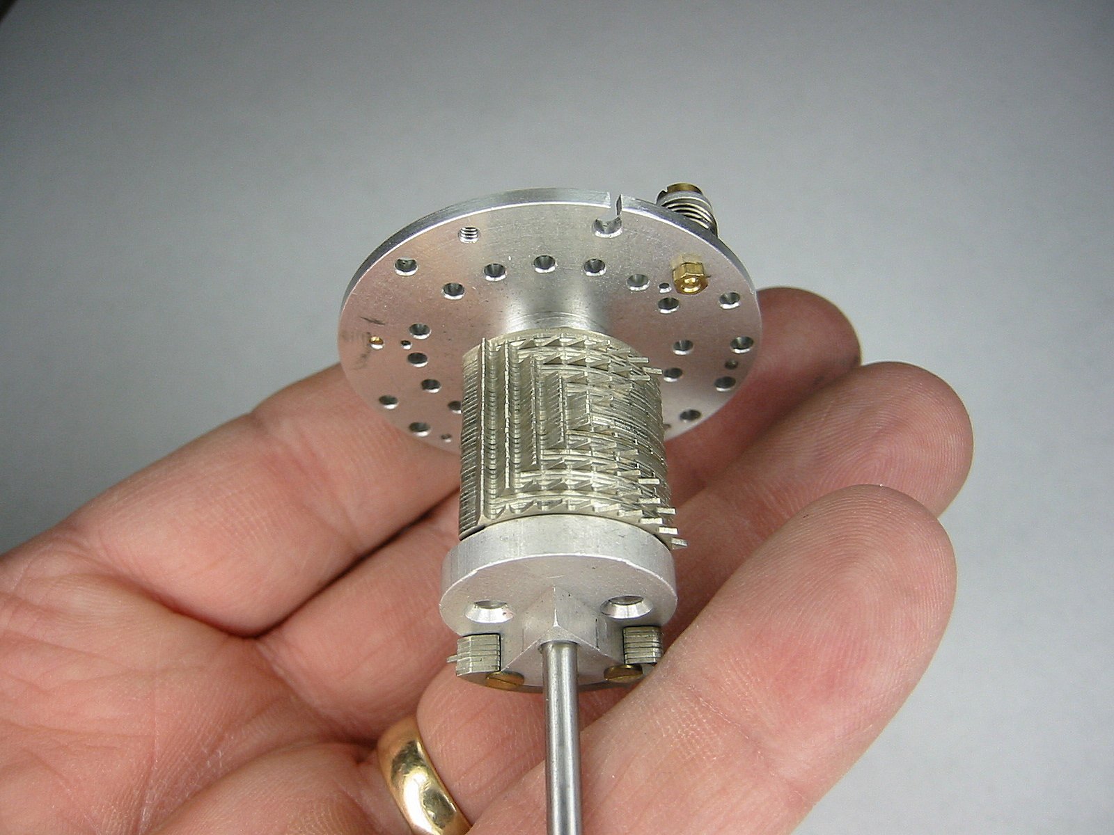
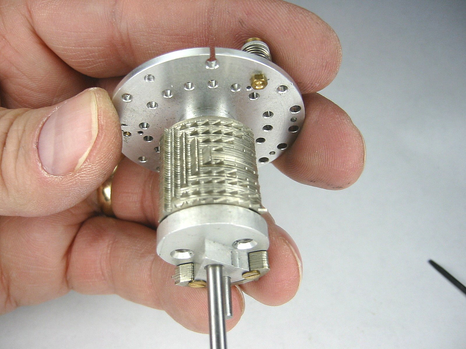
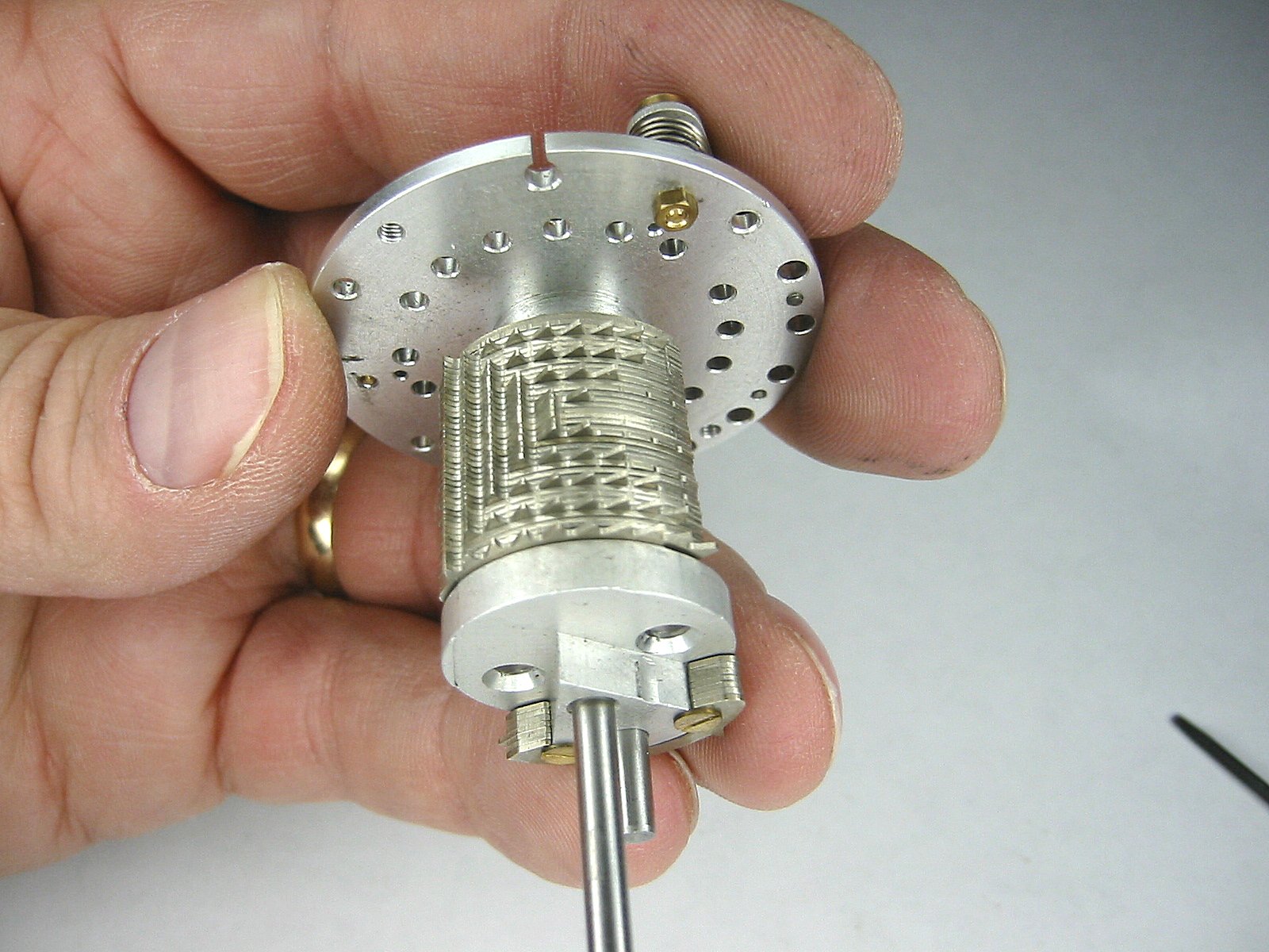
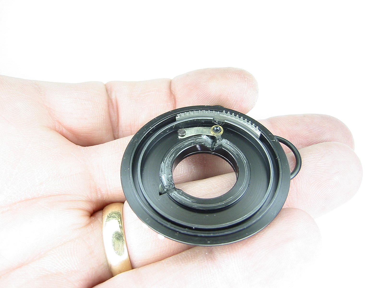
The Step drum can new be easily seen. The big section is used with the main accumulator. |
The small section (on the other side) is used with the turns counter accumulator. |
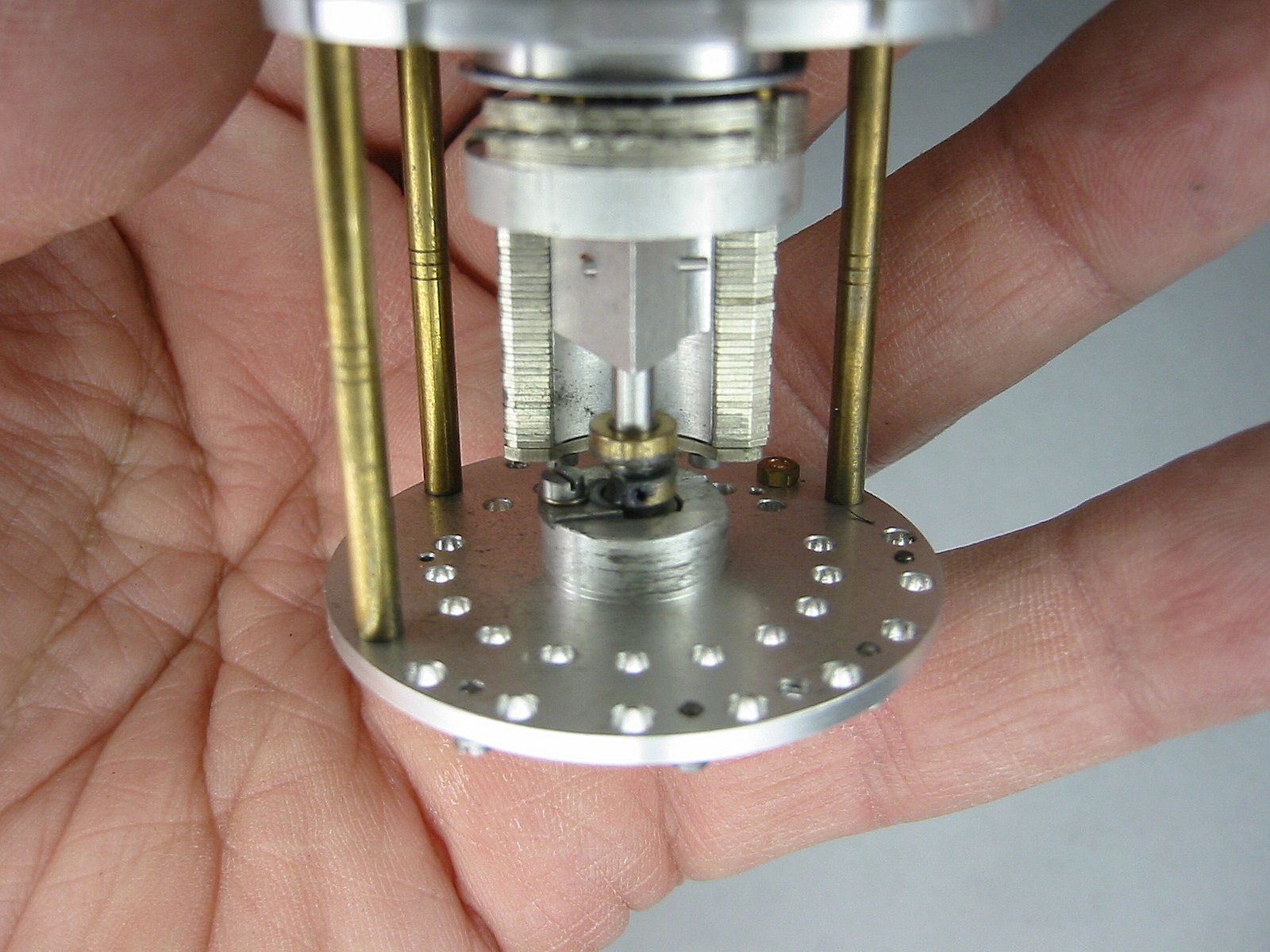
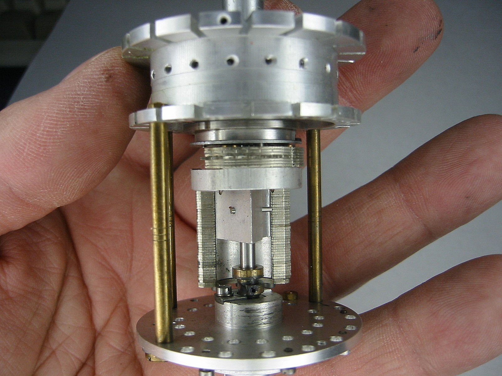
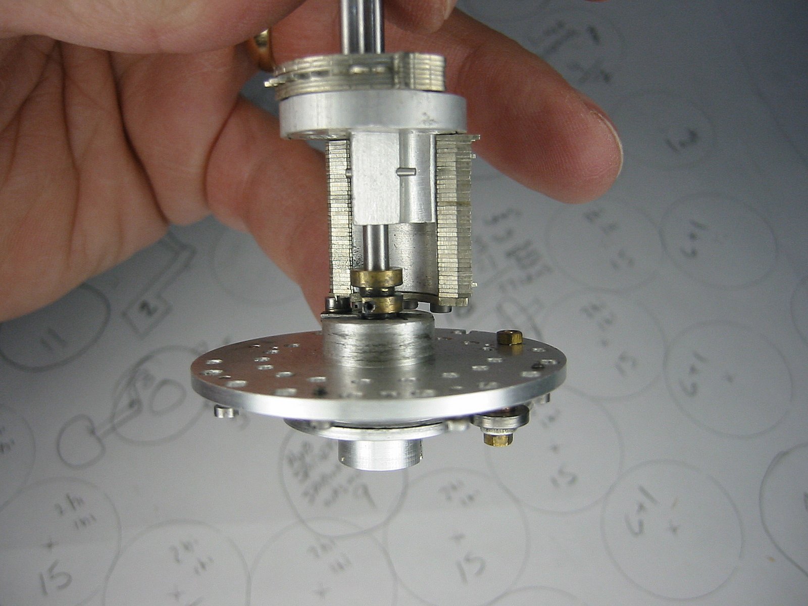
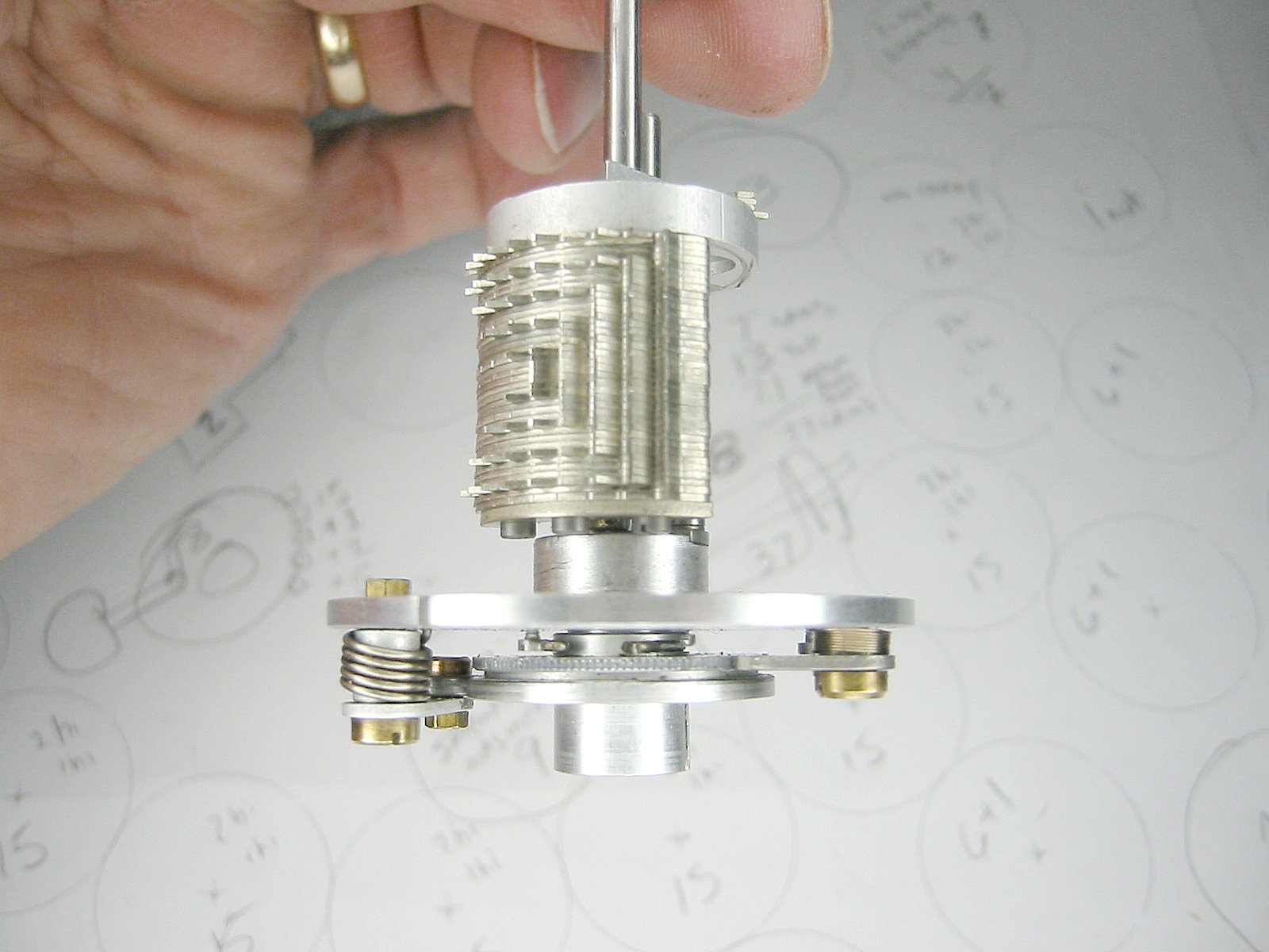
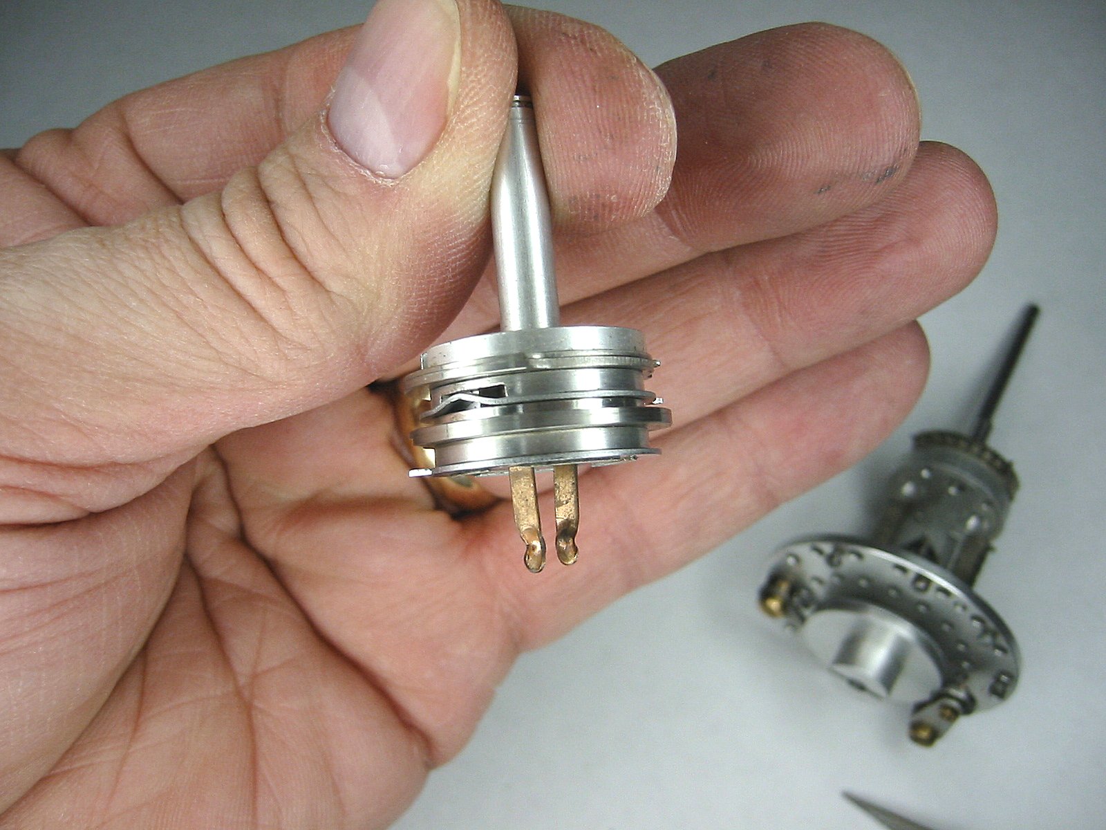
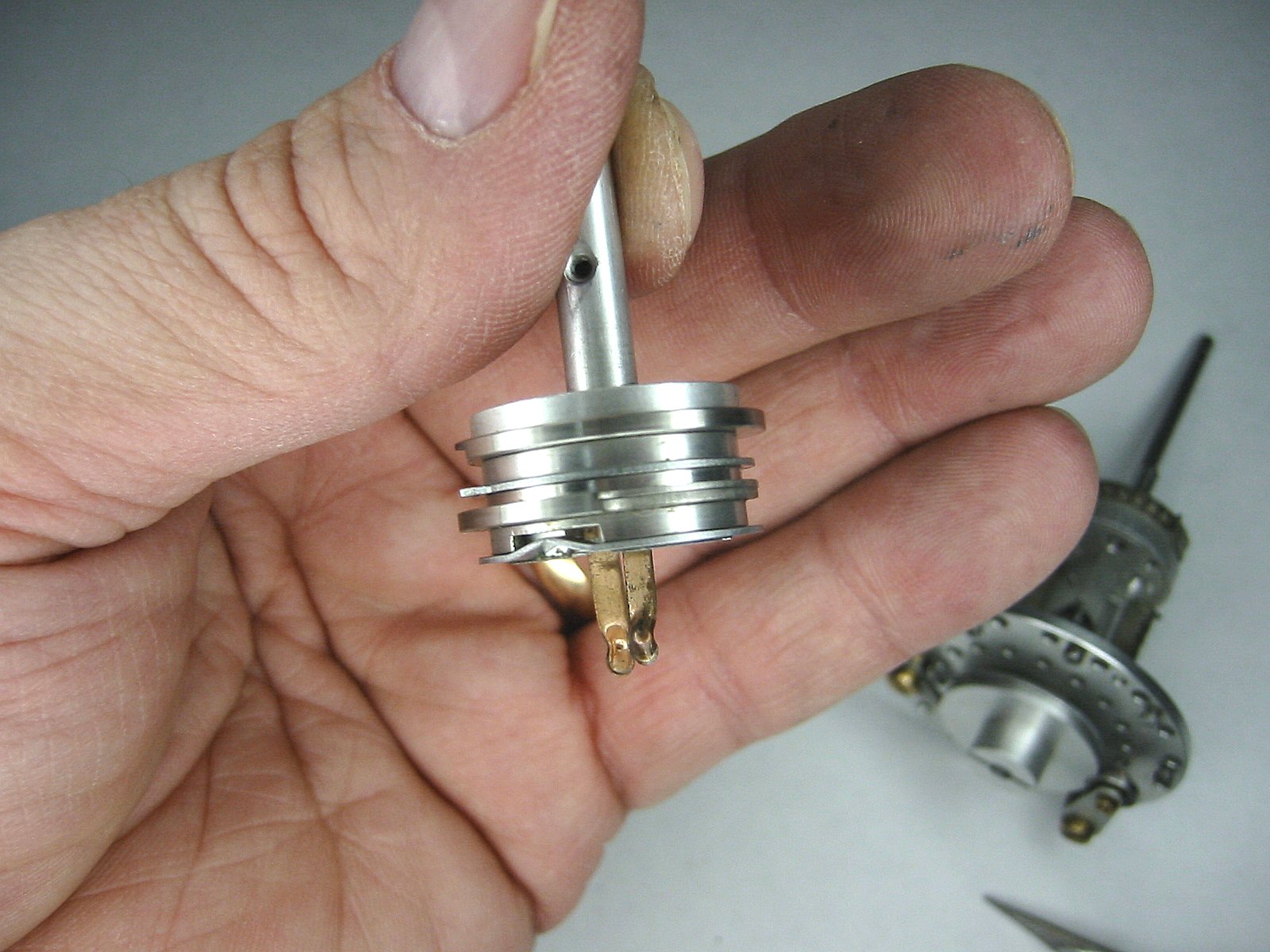
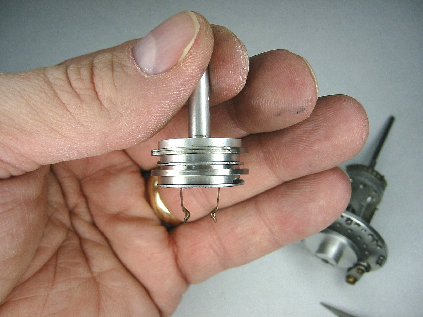
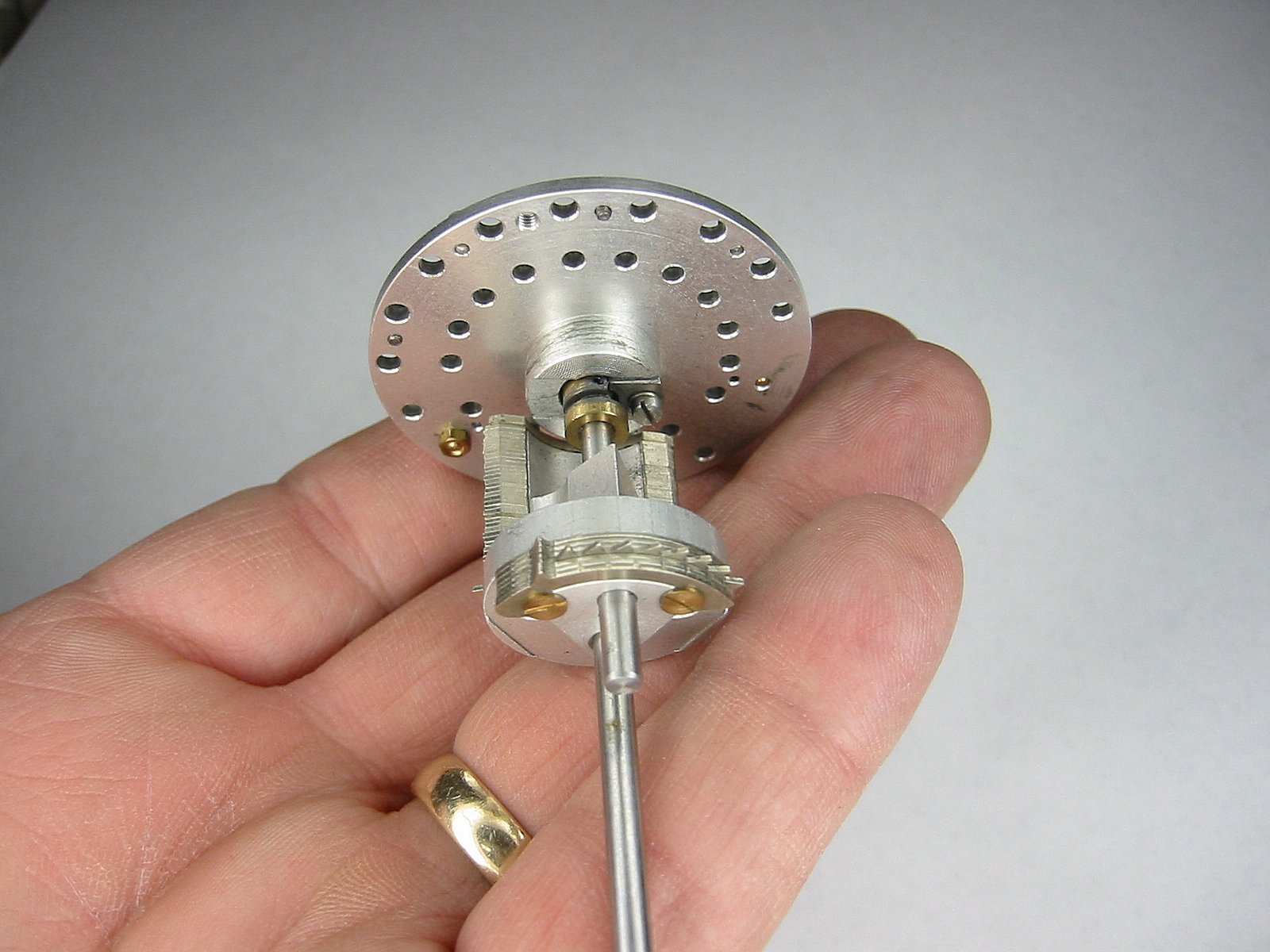
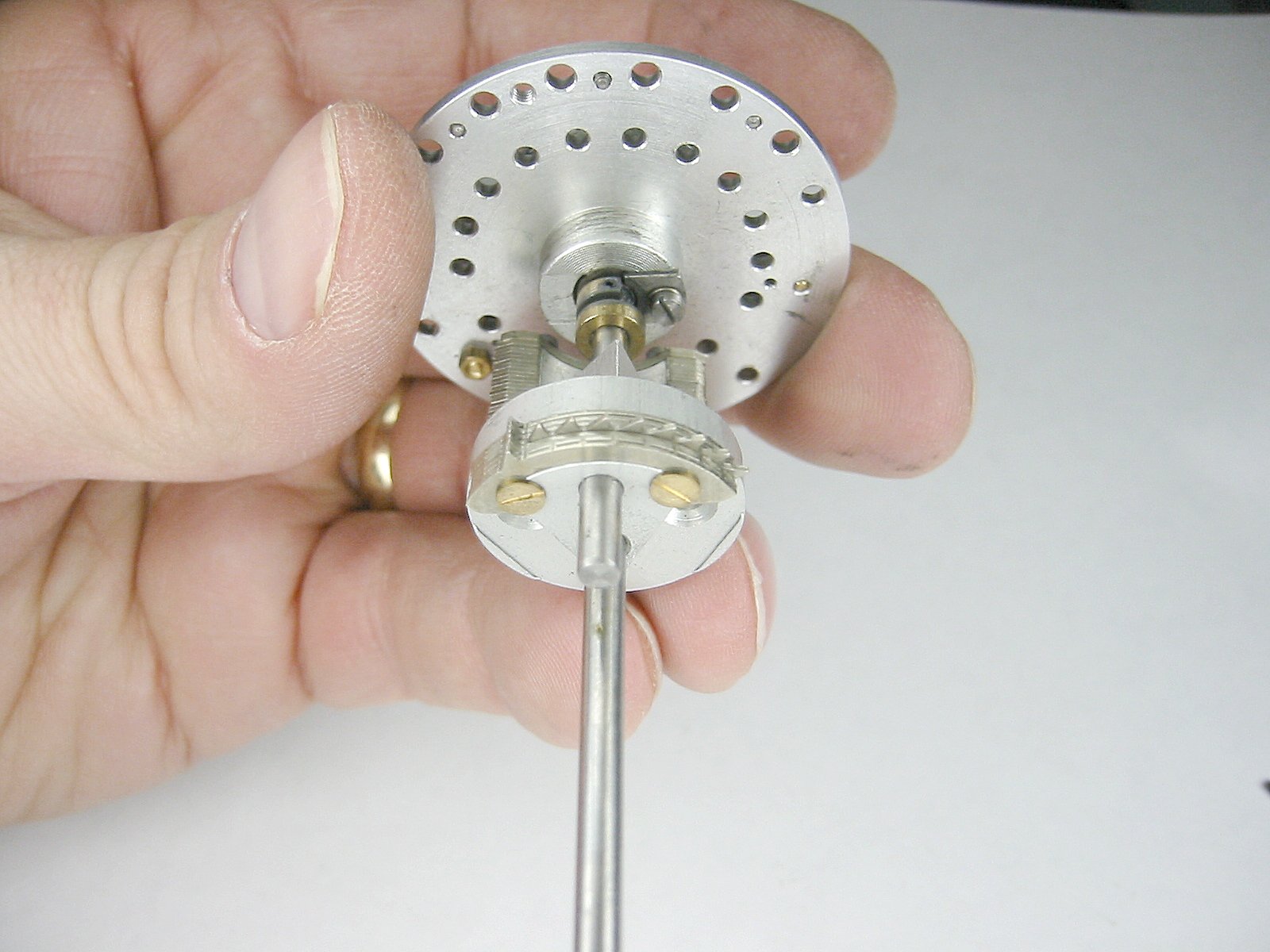
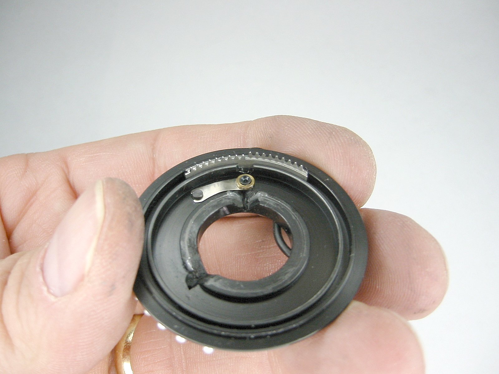
The brass cam at the bottom of the shaft is an interlock that is used to prevent the turns handle from being lifted or pushed down once a turn is initiated. |
The brass cam at the bottom |
The brass cam at the bottom |
The brass cam at the bottom |
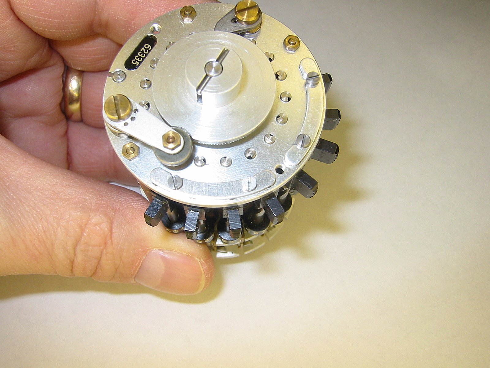
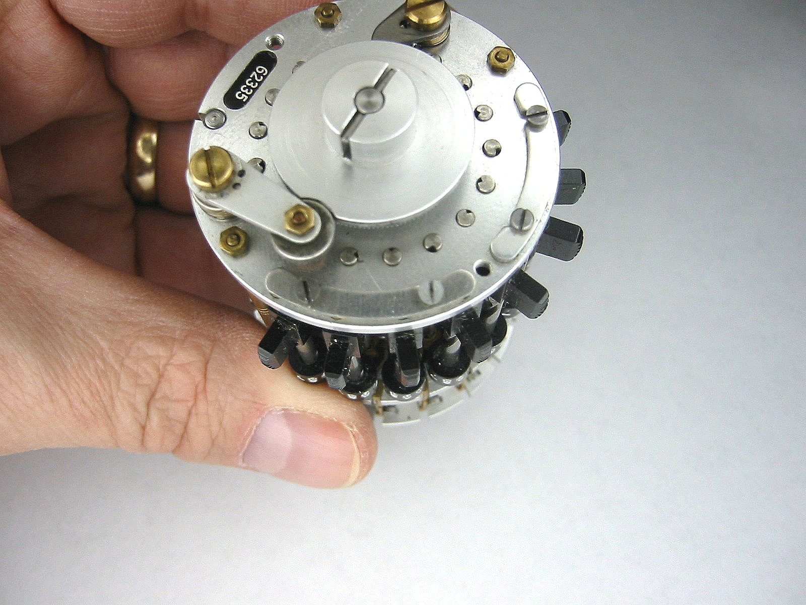
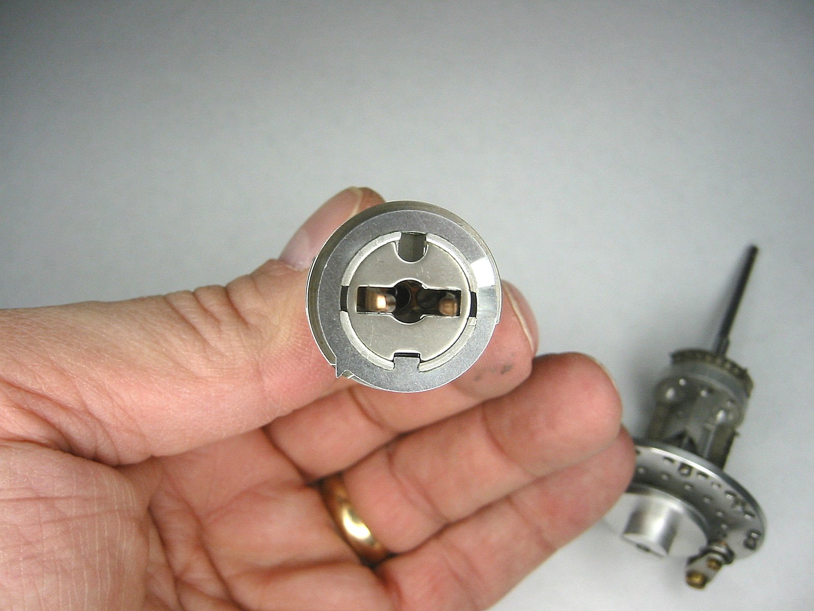
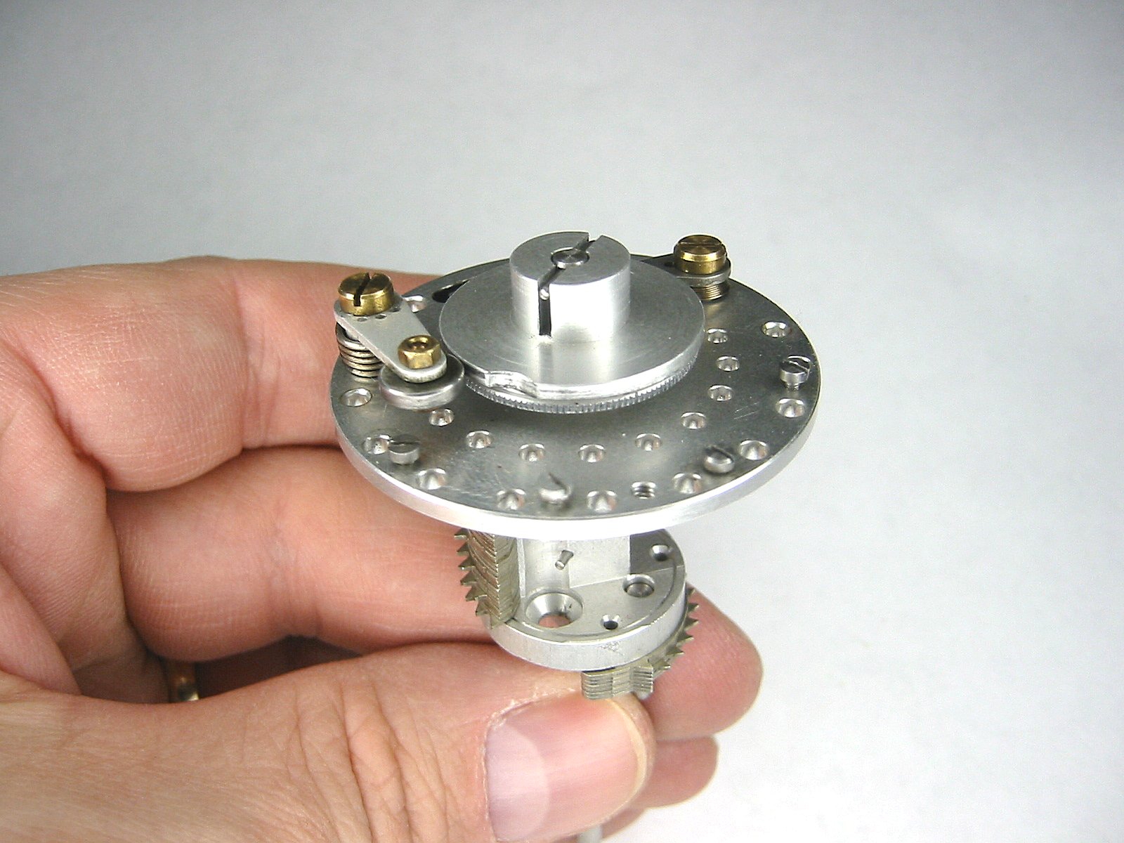
The top |
Now remove the three brass nuts on the bottom of the Curta. This will allow the top plate to be separated from the bottom plate. |
Here's the separated bottom. |
The bottom separated |
The bottom separated |

The bottom separated |
The bottom separated |
Here's the top |
The top separated |
The top separated |
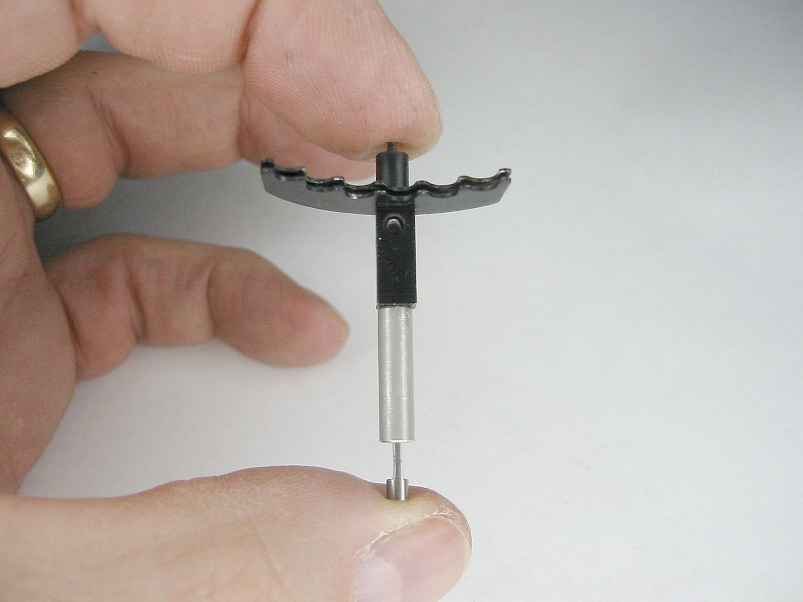
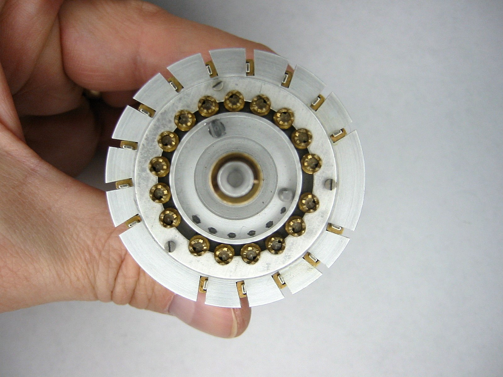
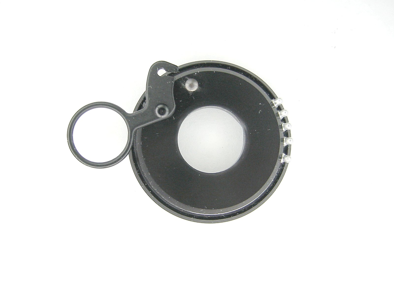
The tens bell can be freed up by removing the small c-clip on the top of the main shaft housing. |
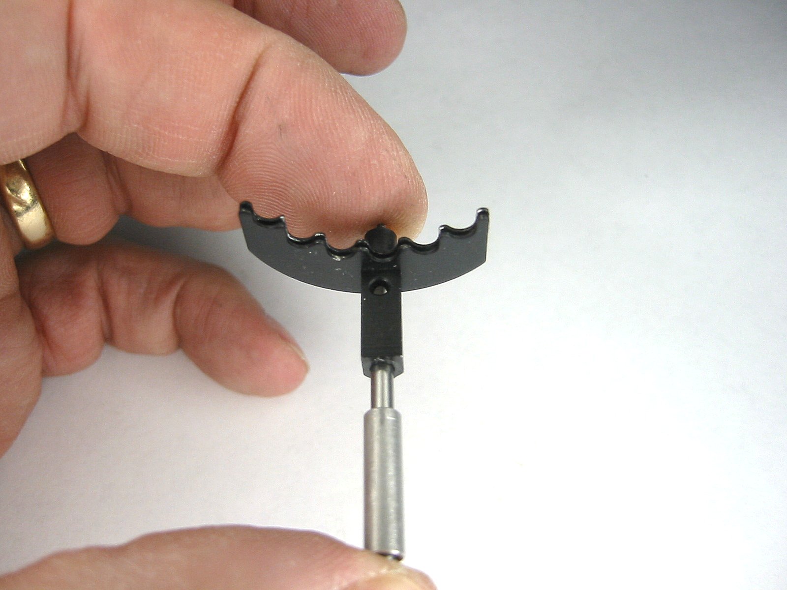
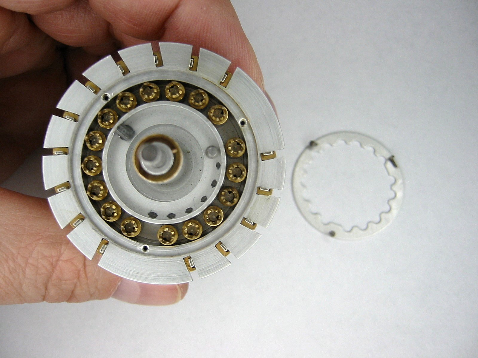
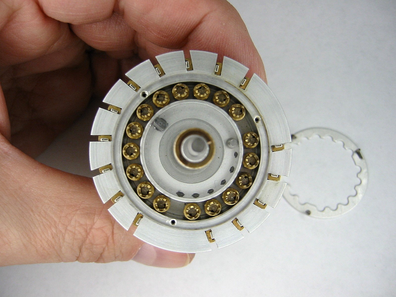
This is the tens bell. It is used to control the logic of the tens carry mechanism. |
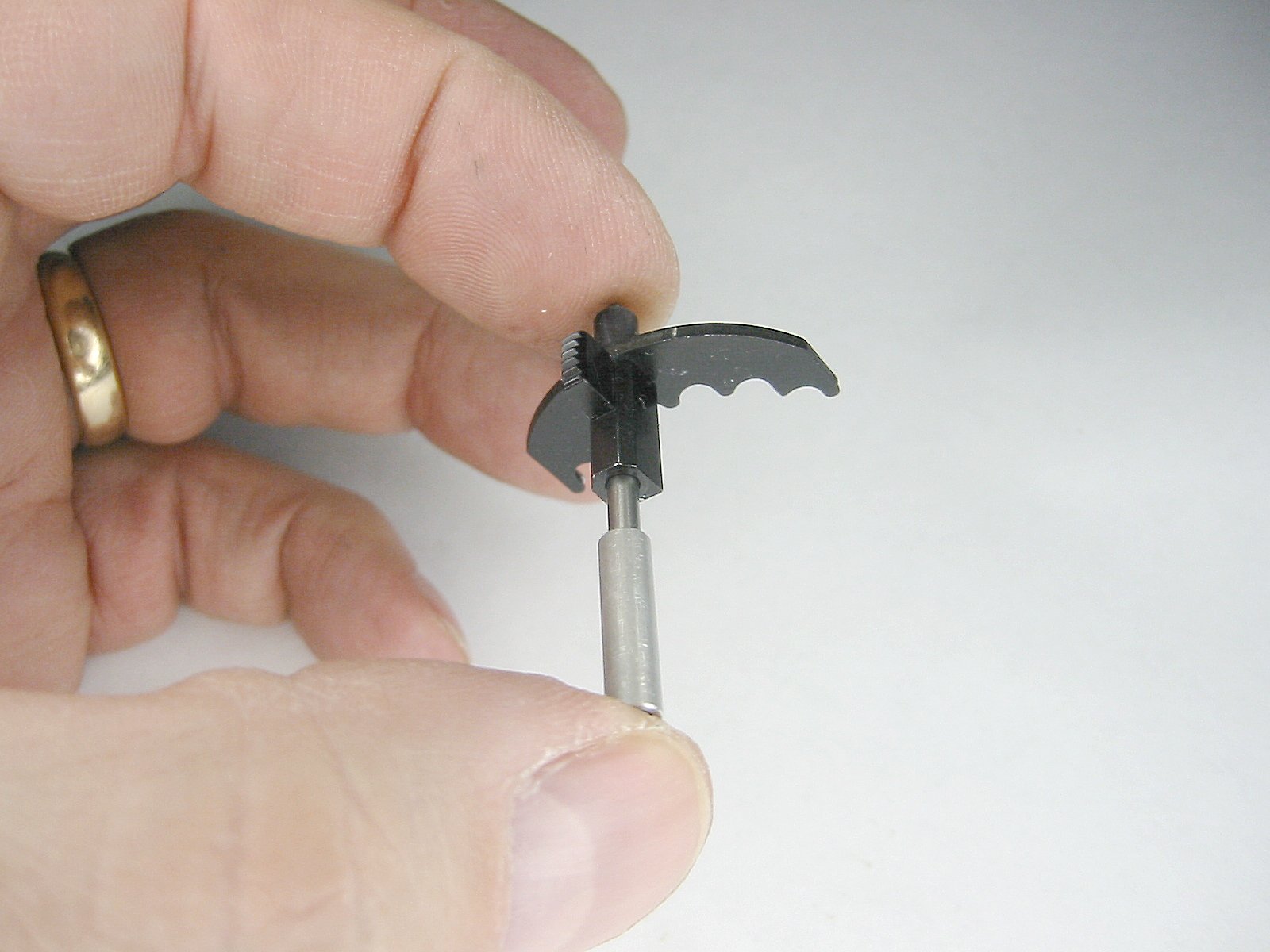
The bottom level is used to clear the carry levers to a "no carry" or up position on the main accumulator. The raised portion of this ring is the point where the tens carry levers get pushed up. The third level is just like the bottom level except it is used with the turns counter accumulator. |
The next level up is used to prevent the transmission shafts from turning except when the mechanism is in a position that would be appropriate for motion to occur. The forth level up is like this one except it is used to lock the turns carry transmission shafts when motion is not warranted. |
Notice the notch on the bottom level of the tens bell. This is used to input a count on any shaft where the ten carry position is set. |
The tens bell |
This is the upper main casting. |
The two pins near the center are used to prevent the top carriage from turning past it's 6 shift positions. |
Bottom view of the top assembly |
The bottom assembly |
The bottom assembly |
The bottom assembly |
The bottom assembly |
The bottom assembly |
The step drum |
The step drum |
The step drum |
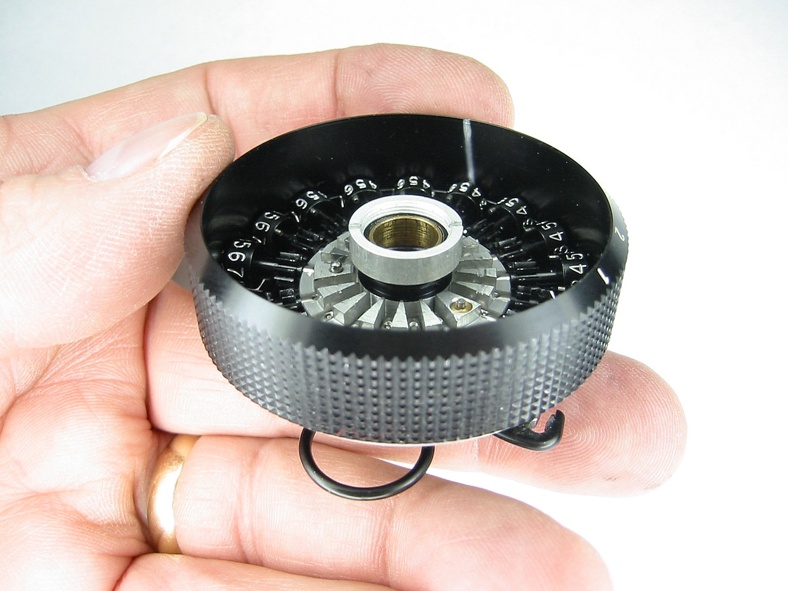
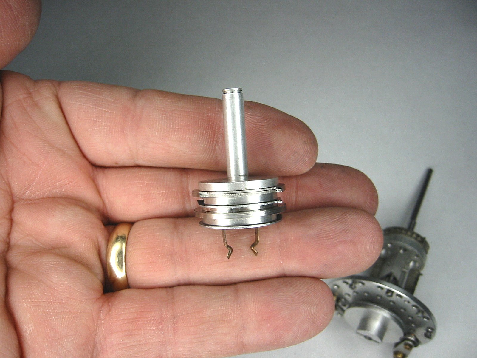
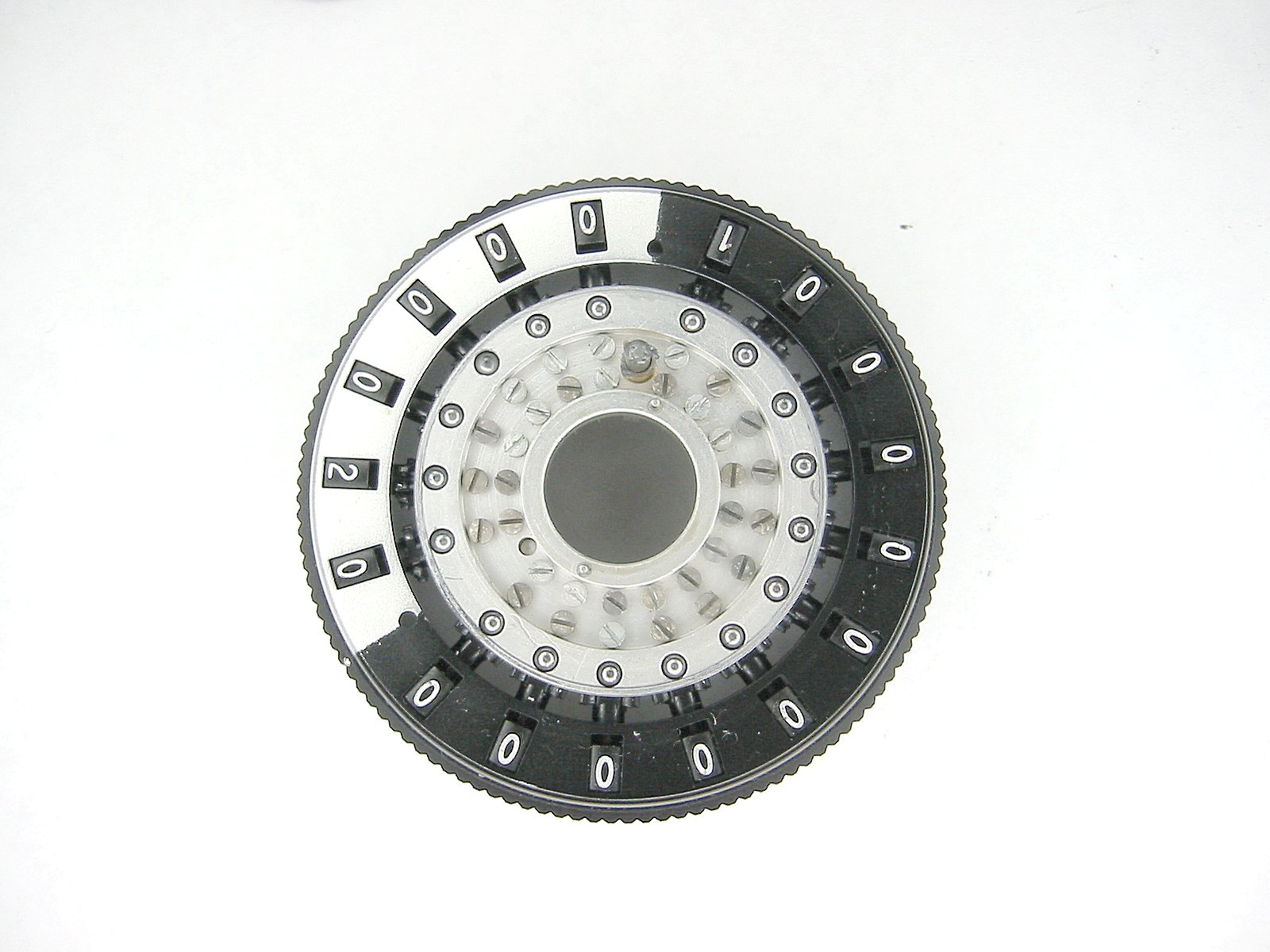
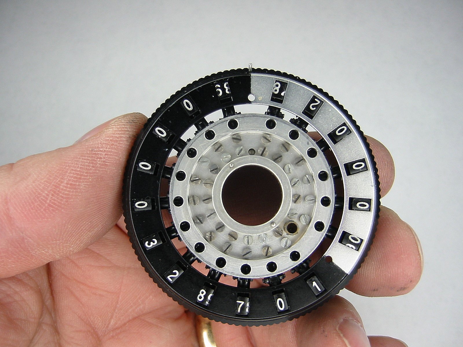
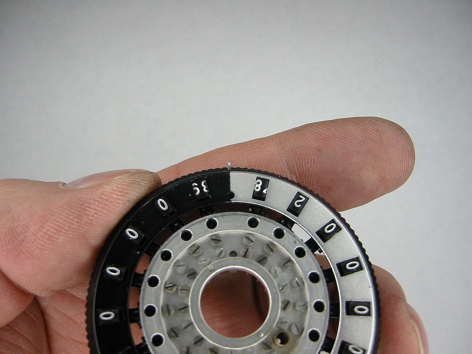
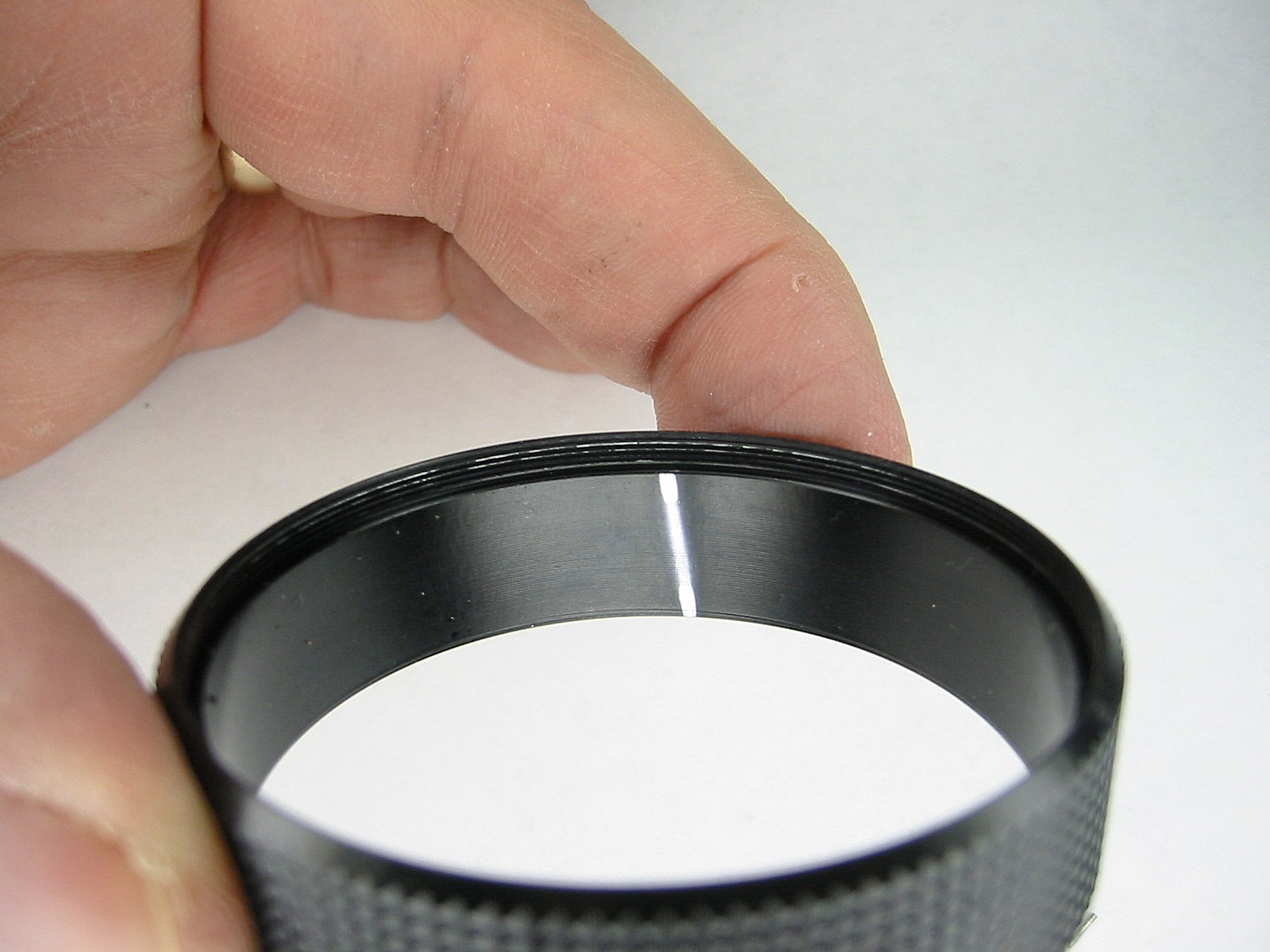
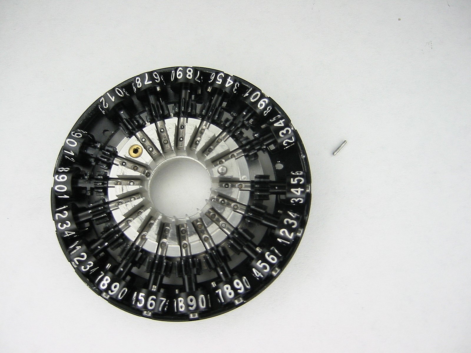
Now to the top carriage. Remove the nut on the center shaft. |
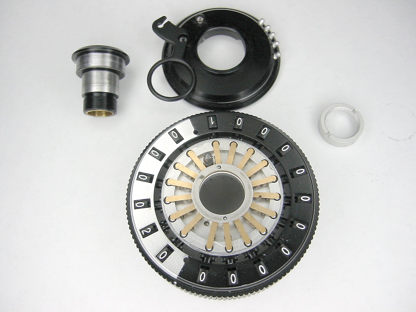
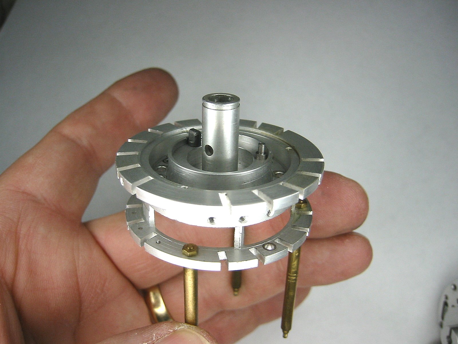
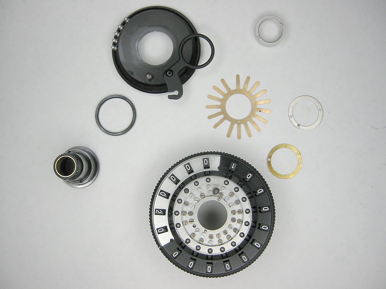
Carefully lift the top sleave out. The carriage must be kept flat and upright as there are 18 ball bearings under the spider spring. Then lift the clearing plate off. |
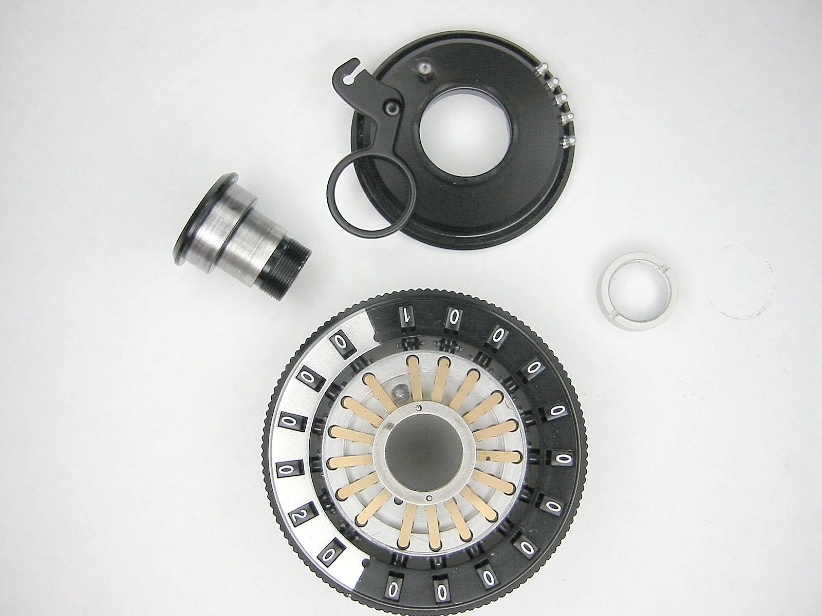
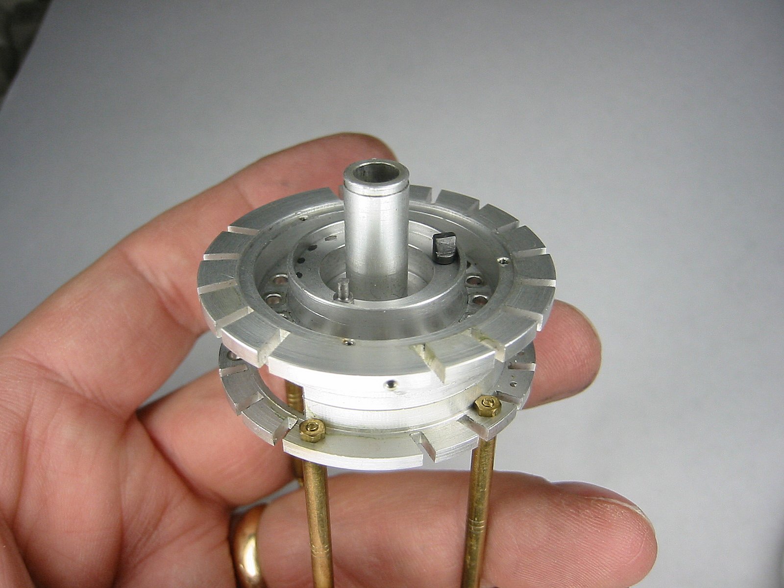
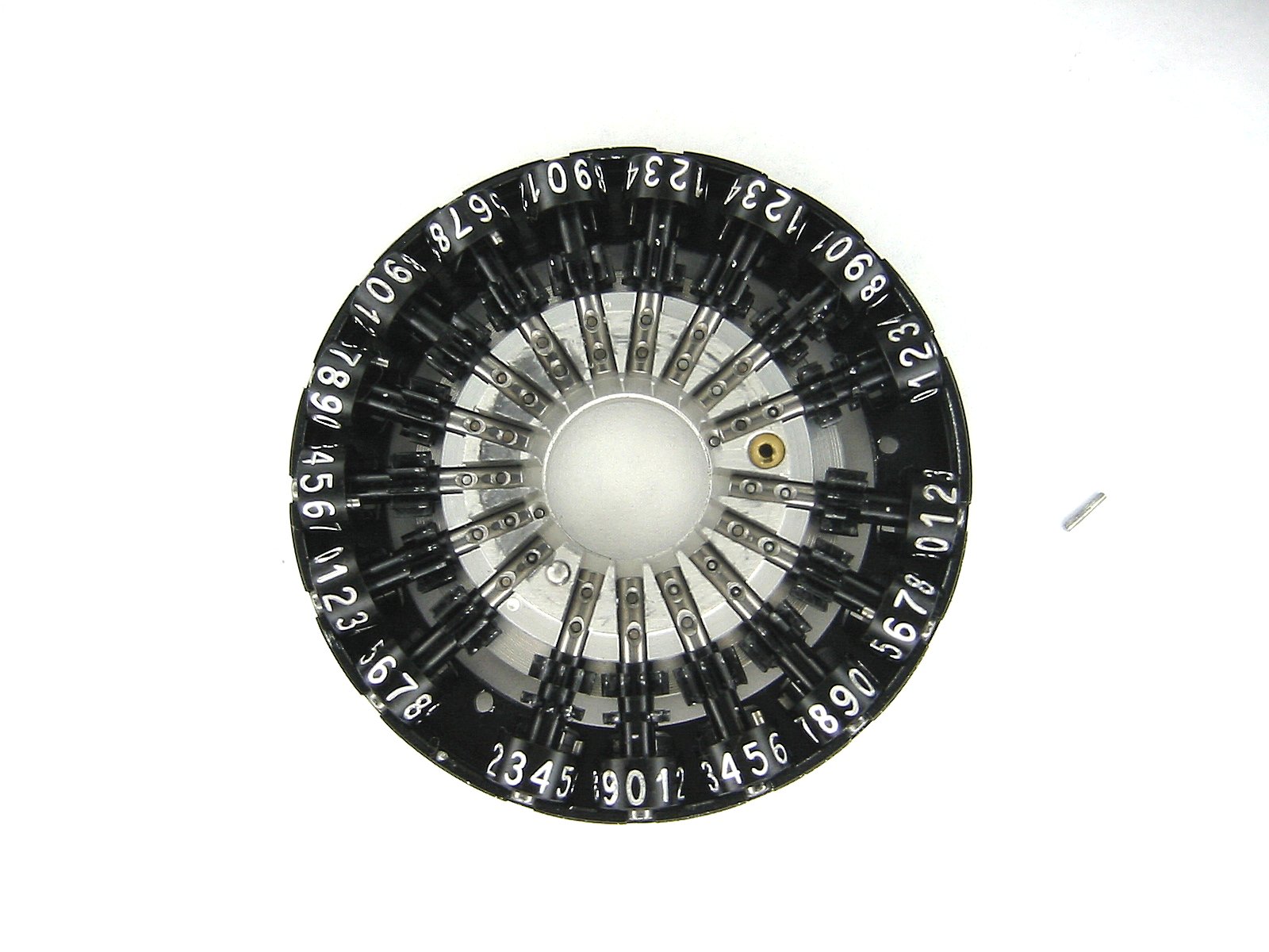
Now the spider spring can be seen. |
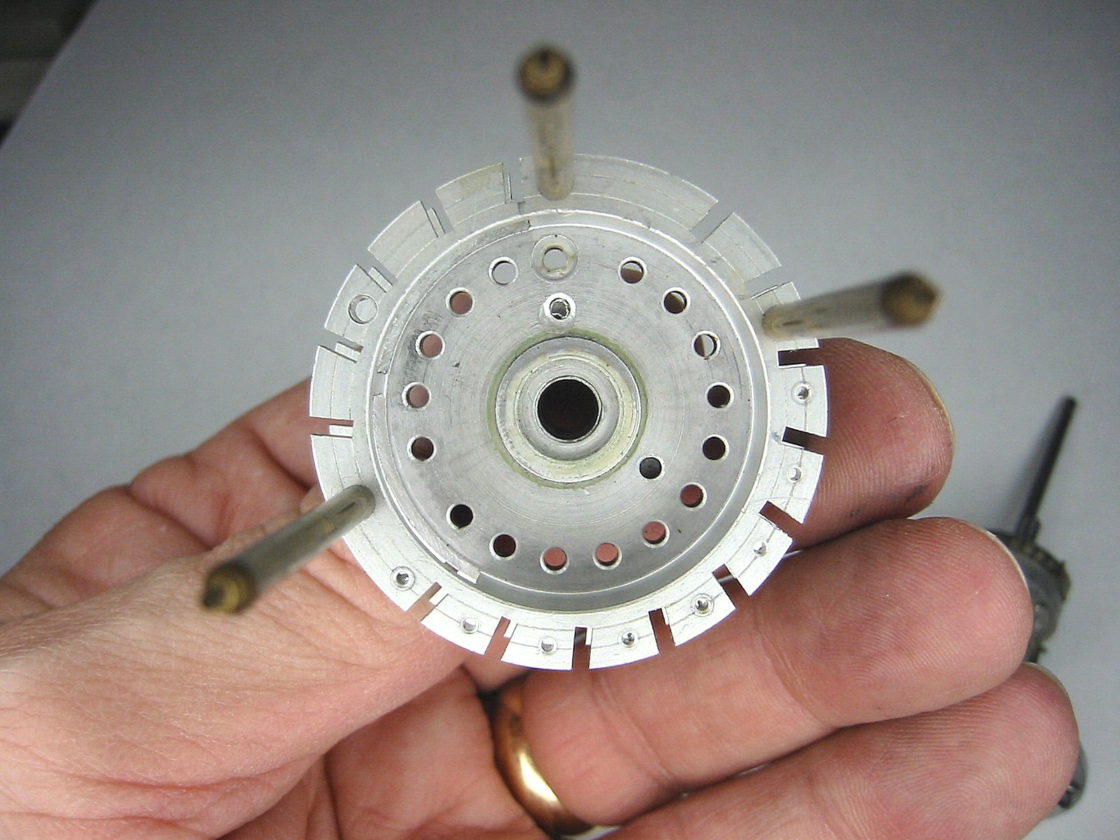
There are two flat washers on top of the spider spring. Once they are all removed the carriage casting can be studied. The 17 ball bearings provide the positive numeral dial positioning. |
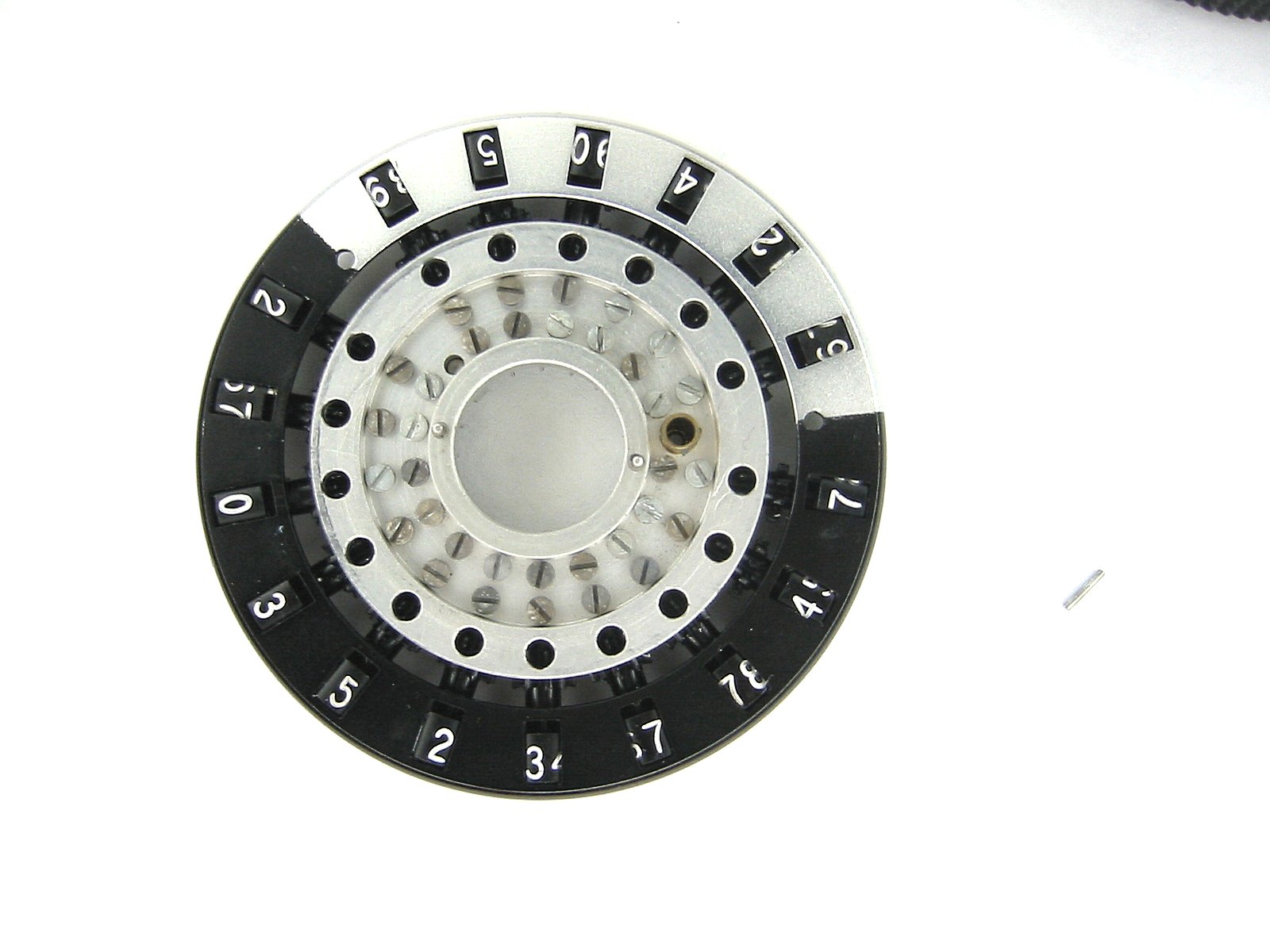
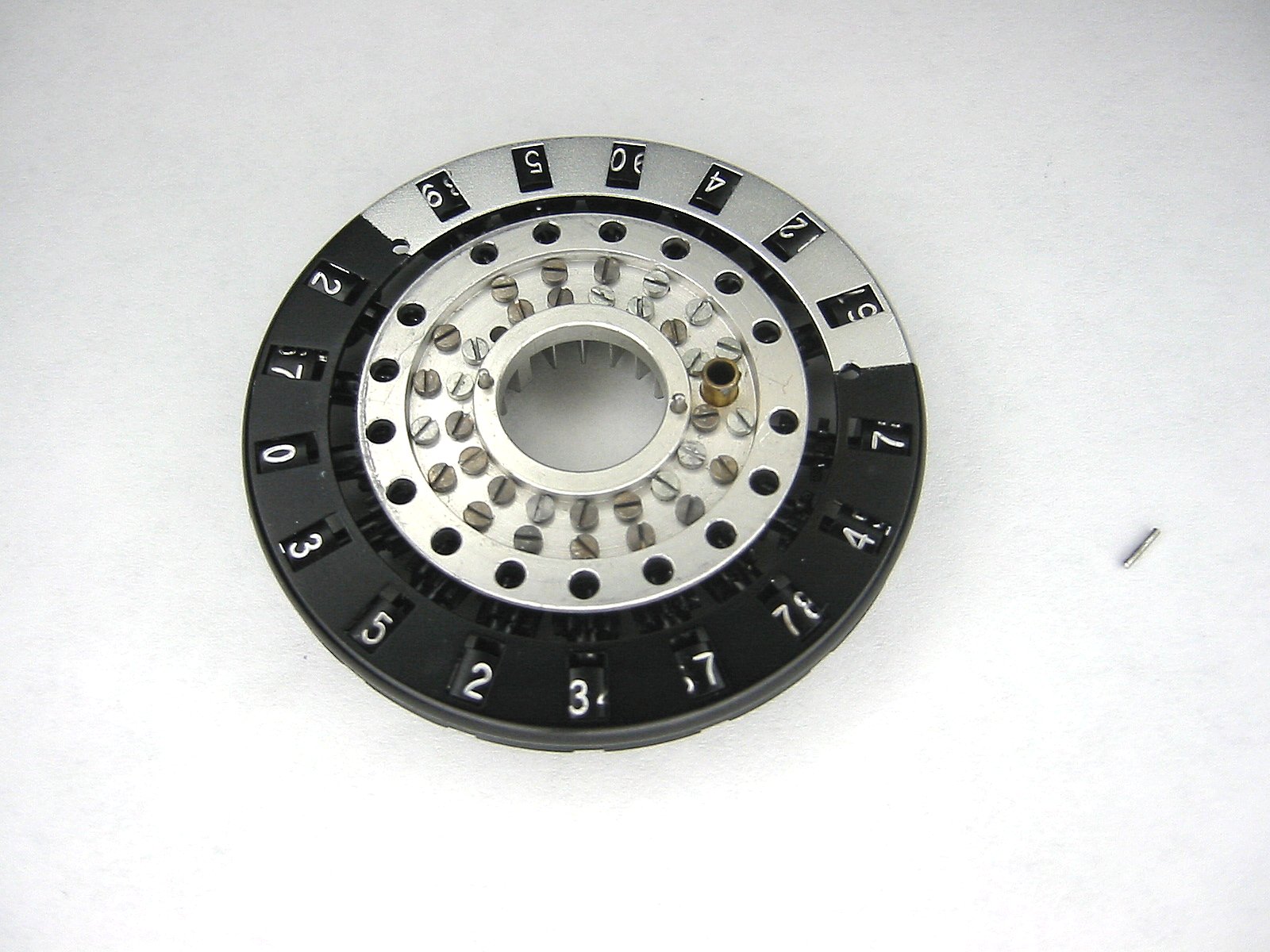
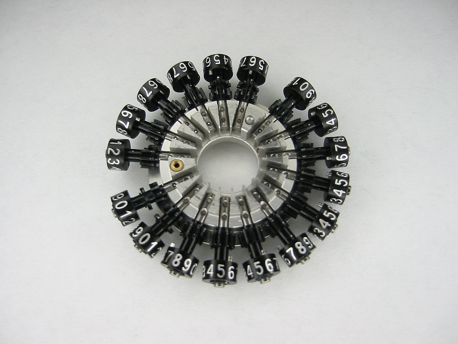
The top carriage |
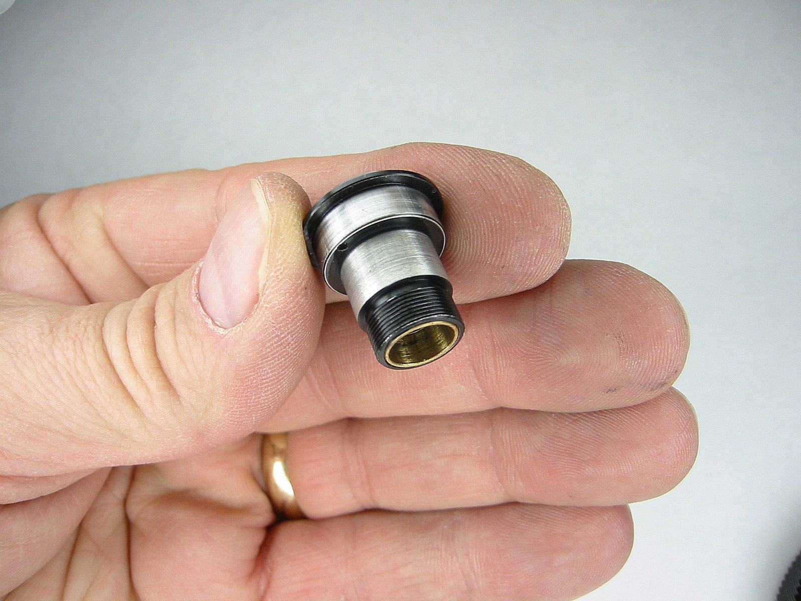
The center shaft |
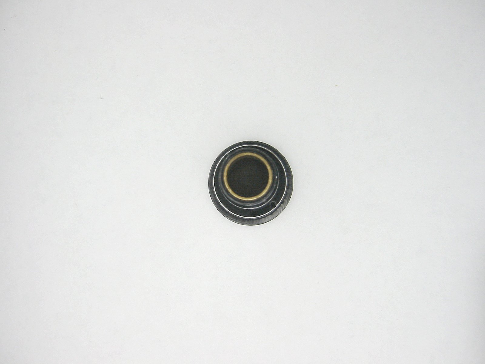
There's a brass sleeve on the inside of the center sleeve. |
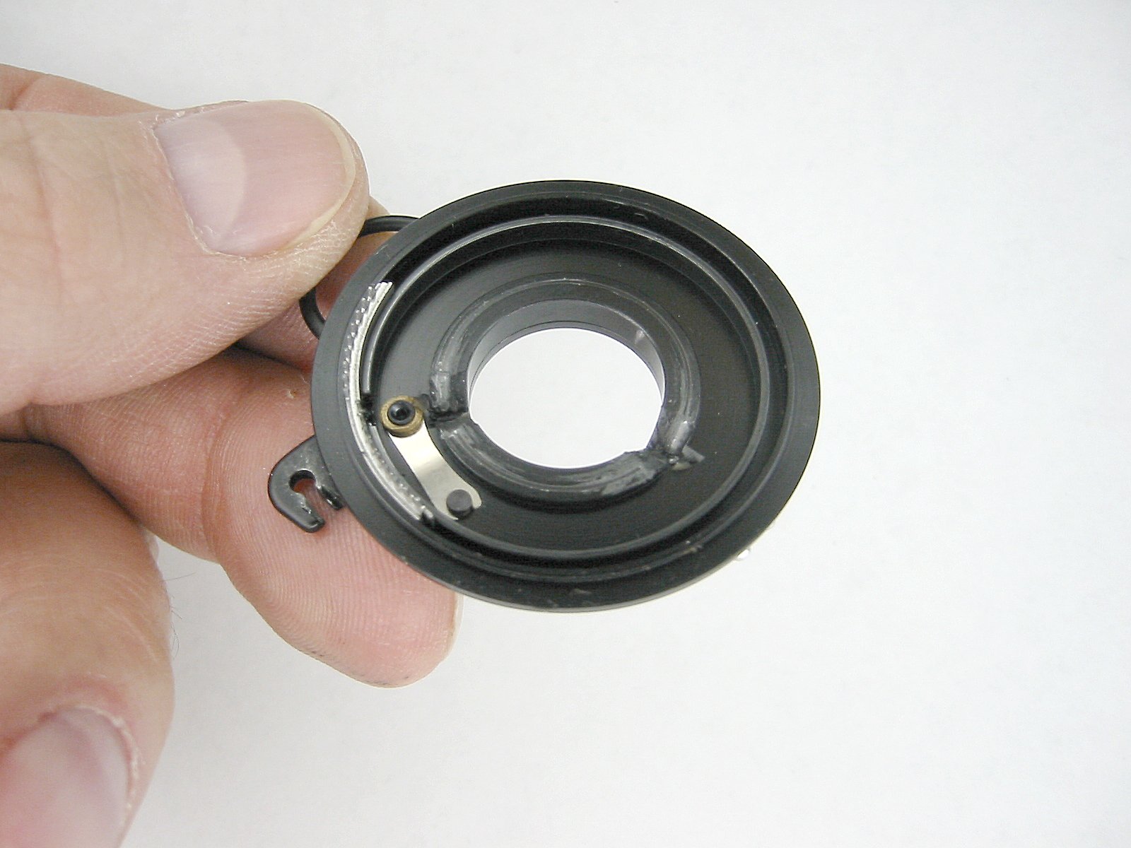
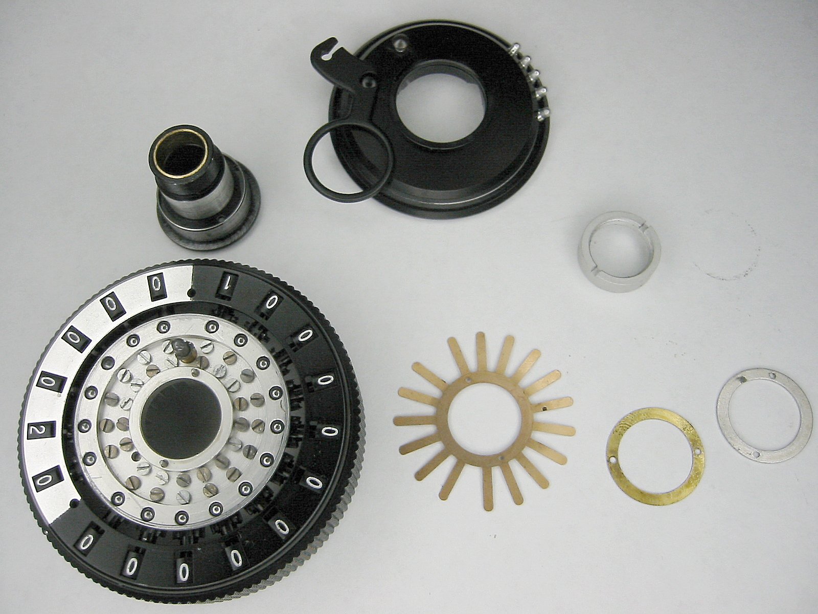
Here's the bottom of the clearing plate. |
The linear gear (actually it's three laminations) turn each numerical dial to it's home or zero position. |
The clearing plate |
The clearing plate |
Here are all of the main clearing plate parts. |
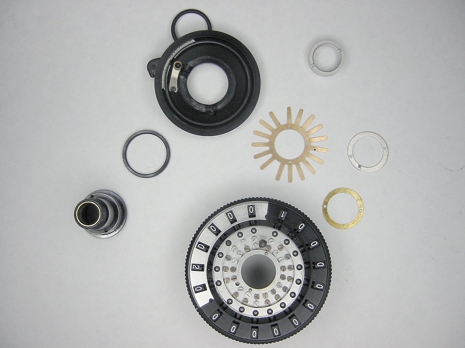
The clearing plate parts |
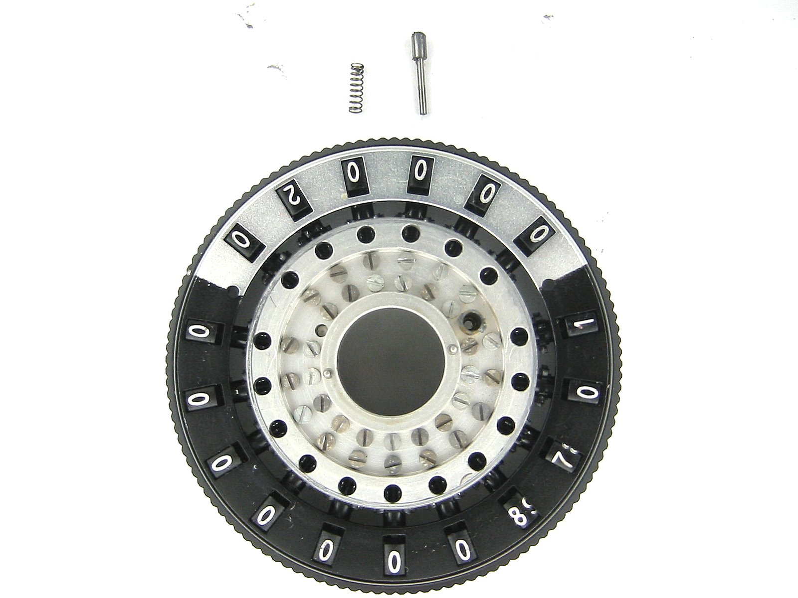
To the left of the "1" a brass shaft can be seen. The plunger and spring at the top come out of this shaft. This mechanism keeps the clearing plate from turning unless the carriage is lifted. |
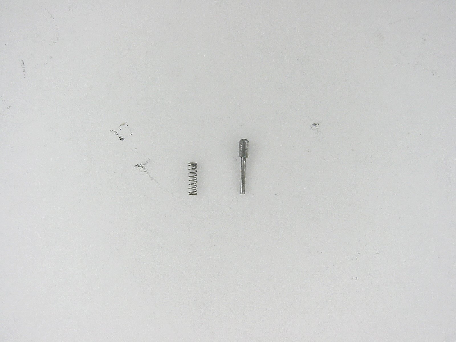
The plunger and spring |
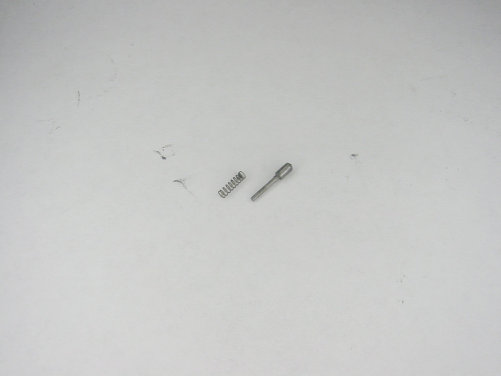
The plunger and spring |
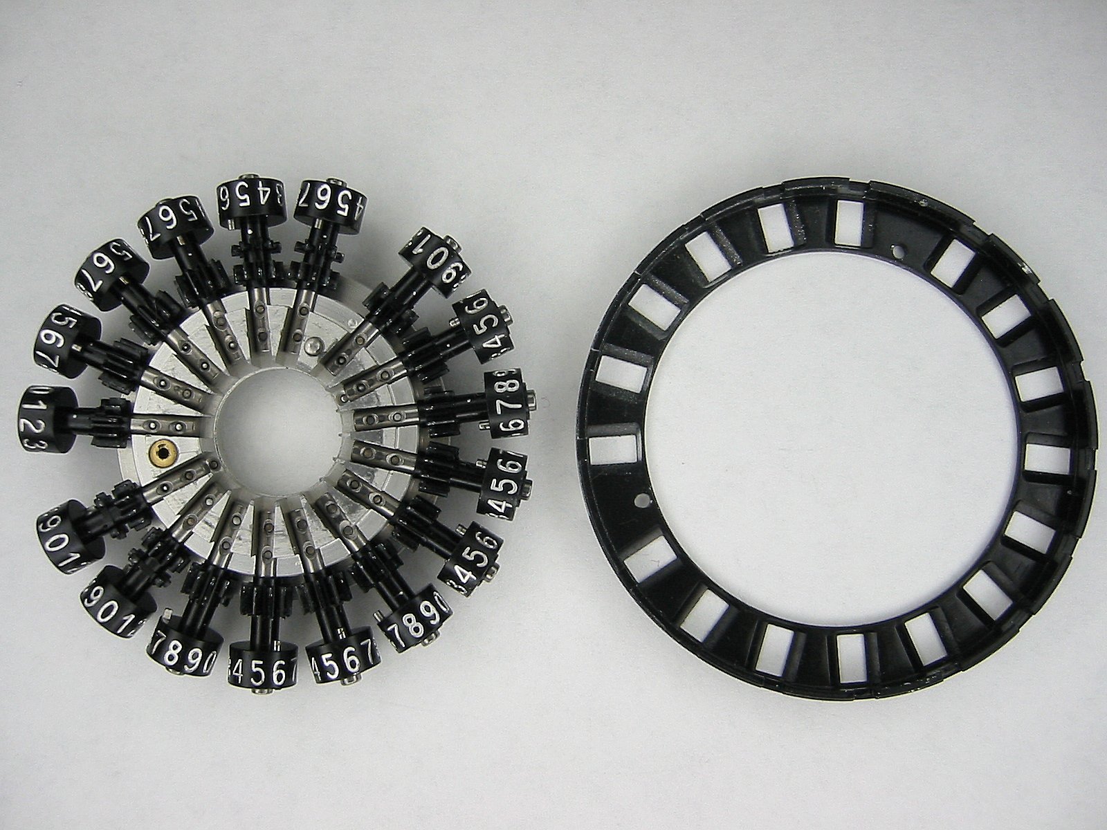
The top carriage less the clearing plate, springs, washers, and ball bearings. |
This little pin presses out from the inside. |
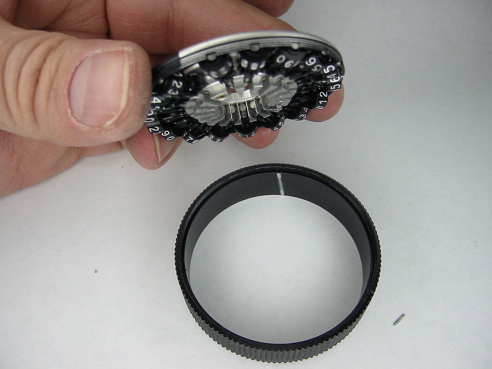
Once the pin is out the cage can be unscrewed from the carriage ring. |
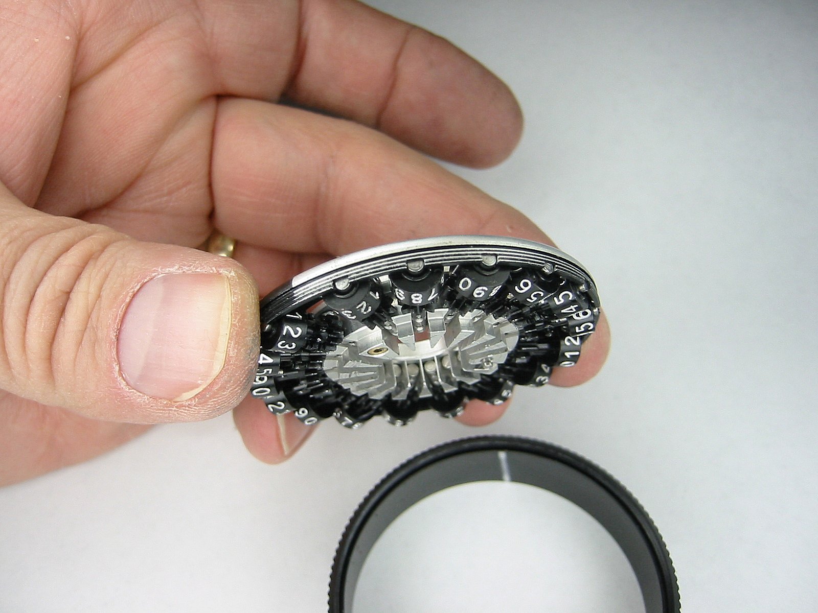
The top carriage cage assembly |
The carriage ring. |
This is the bottom of the cage with the carriage casting and axles. |
The top carriage cage assembly |
The top carriage cage assembly |
The pin just to the right of the center ring works in conjunction with the two pins in the top of the upper main casting to prevent the top carriage from turning past it's 6 shift positions. |
The carriage casting and axles can be snapped out of the cage. |
DO NOT remove the axles from the carriage casting. |
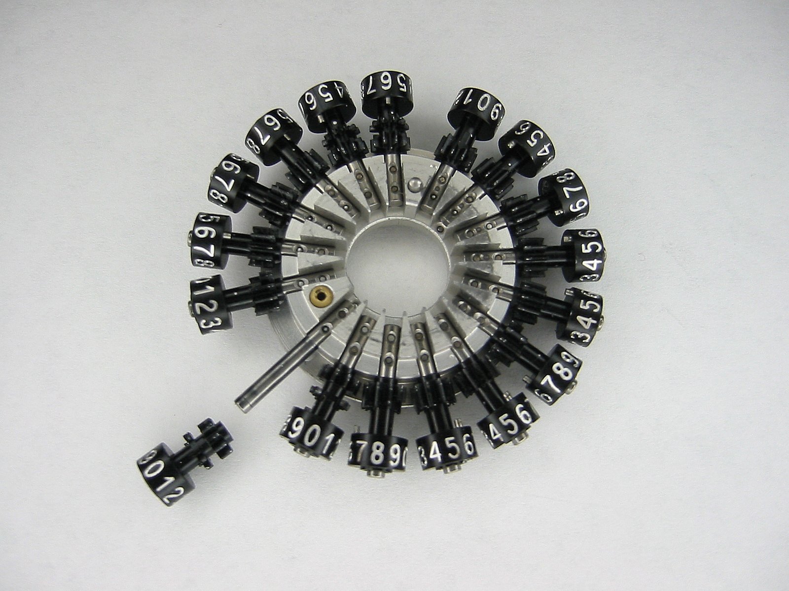
The numerical dials can be slid off of the axles. |
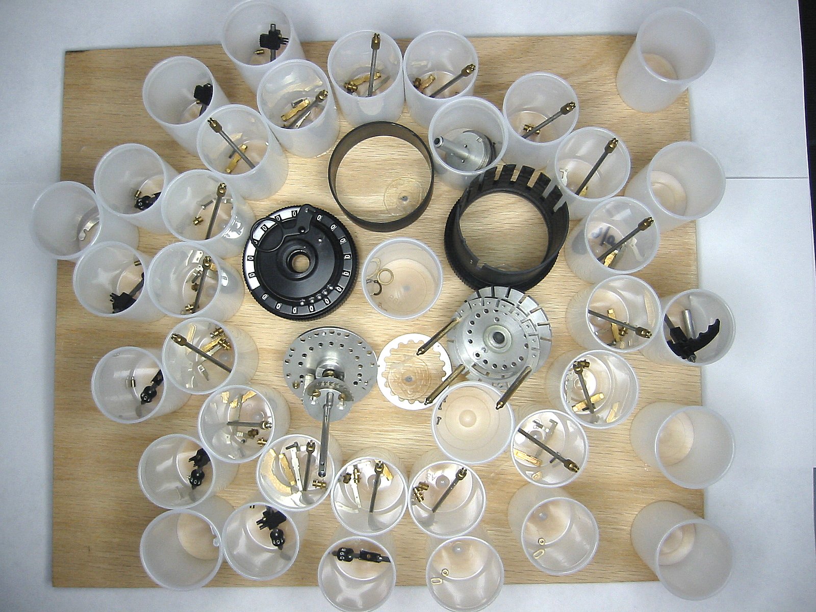
So here how I kept it all straight. Film cans hot glued to a piece of plywood! It's real important to return each part to their original position. Many are hand fit so put them back the way they were! |
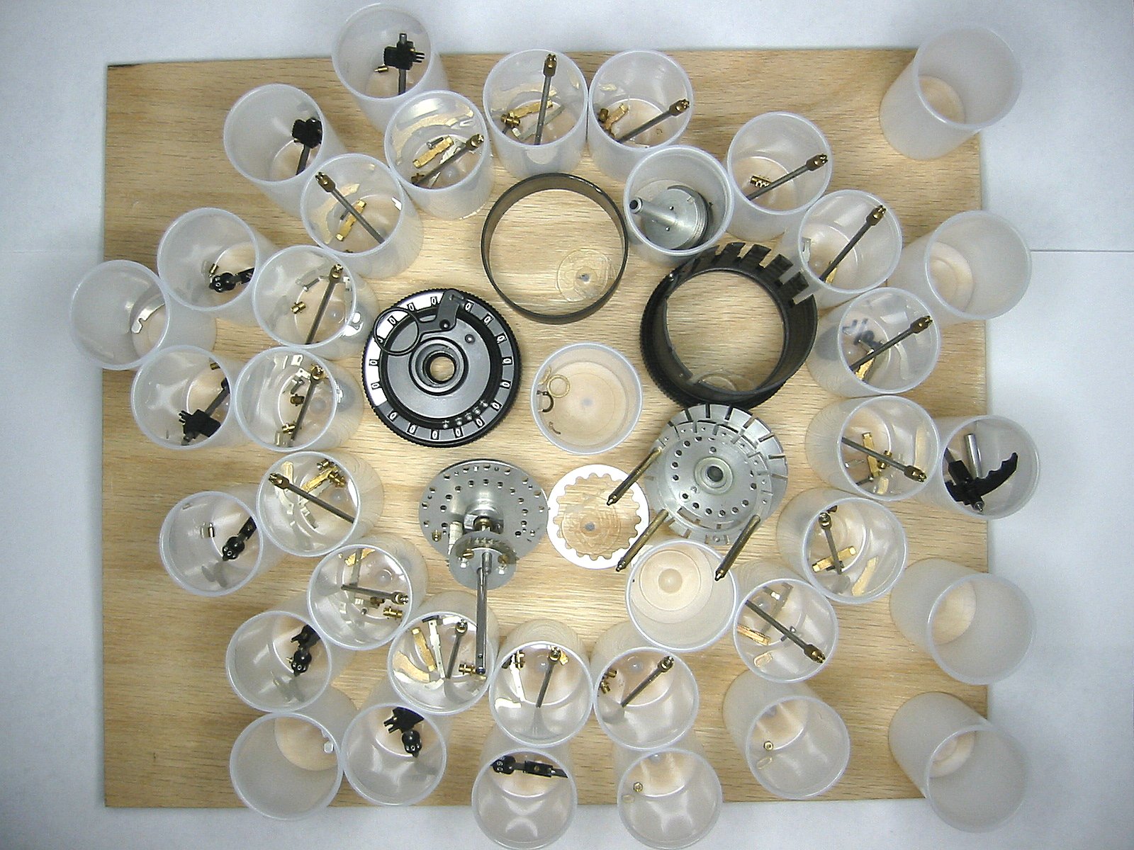
And how many parts are there in a Curta? It's official, there are 605 parts counting the metal storage can! |
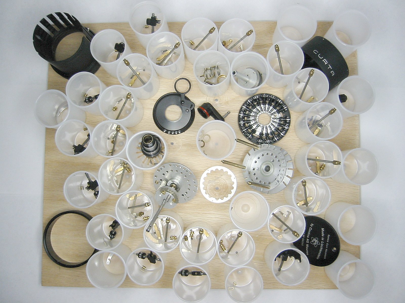
Thanks to my good friend Carl Volkmar who loaned me his entire Curta collection to study and make this presentation from. There's also a poster that shows all of these parts of the Curta and their names. |